Product Description
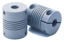
GB 8 Fonts Encoder-specific Series coupling Special aluminium alloy coupling for encoder
Description of GB 8 Fonts Encoder-specific Series coupling Special aluminium alloy coupling
>Designed for encoder
>Good flexibility, not easy to break
>The elastomer is made of polyurethane, resistant to oil and oxidation
Dimensions of GB 8 Fonts Encoder-specific Series coupling Special aluminium alloy coupling
| model parameter | common bore diameter d1,d2 | ΦD | L | LP | S | F | M | tightening screw torque (N.M) |
| GB-15X24 | 3,4,5,6,6.35,7,8 | 15 | 24 | 20 | 1.8 | 2.5 | M3 | 0.7 |
| GB-15×32 | 3,4,5,6,6.35,7,8 | 15 | 32 | 20 | 1.8 | 2.5 | M3 | 0.7 |
| GB-18×28 | 4,5,6,6.35,7,8,9,10 | 18 | 28 | 25 | 1.8 | 3.1 | M4 | 1.7 |
| GB-18×38 | 4,5,6,6.35,7,8,9,10 | 18 | 38 | 25 | 1.8 | 3.1 | M4 | 1.7 |
| model parameter | Rated torque (N.M)* |
allowable eccentricity (mm)* |
allowable deflection angle (°)* |
allowable axial deviation (mm)* |
maximum speed rpm |
static torsional stiffness (N.M/rad) |
moment of inertia (Kg.M2) |
Material of shaft sleeve | Material of shrapnel | surface treatment | weight (g) |
| GB-15X24 | 0.5 | 1 | 2 | + 2-5 | 8000 | 15 | 4.5×10⁻⁴ | High strength aluminum alloy | PU |
Anodizing treatment |
8 |
| GB-15X32 | 0.5 | 1 | 2 | + 2-5 | 8000 | 15 | 4.5×10⁻⁴ | 8 | |||
| GB-18X28 | 0.8 | 1 | 3 | + 2-5 | 6000 | 20 | 5.6×10⁻⁴ | 13 | |||
| GB-18X38 | 0.8 | 1 | 3 | + 2-5 | 6000 | 20 | 5.6×10⁻⁴ | 13 |
/* January 22, 2571 19:08:37 */!function(){function s(e,r){var a,o={};try{e&&e.split(“,”).forEach(function(e,t){e&&(a=e.match(/(.*?):(.*)$/))&&1
Diagnosing Potential Issues in Encoder Couplings
Identifying potential issues in encoder couplings is crucial for maintaining optimal performance. Some signs to watch for and diagnostic steps include:
1. Signal Inaccuracies: Inaccurate position or velocity feedback signals may indicate coupling misalignment. Use diagnostic tools to compare expected and actual readings.
2. Increased Noise: Unusual vibrations or noise during operation can indicate misalignment or wear. Perform vibration analysis or inspect the coupling for visual damage.
3. Signal Dropouts: Intermittent signal loss or dropouts can be due to poor coupling engagement or damaged wiring. Check wiring connections and the coupling’s mechanical integrity.
4. Drifting Position: If the controlled system’s position drifts over time, it could suggest issues in the encoder coupling’s precision. Monitor position deviations and inspect the coupling for wear.
5. Excessive Heating: Overheating of the coupling may point to misalignment or excessive friction. Monitor the temperature and ensure proper coupling lubrication.
6. Irregular Movement: Unexpected jerks or irregular motion can indicate binding or sticking in the coupling. Inspect the coupling’s components for damage or obstruction.
7. Reduced Accuracy: Decreased accuracy in positioning or velocity control might be due to backlash or wear. Measure and compare desired and achieved positions for accuracy assessment.
8. Excessive Wear: Visual inspection of the coupling’s components for signs of wear, such as cracked or deformed elements, can help detect potential issues early.
9. Misalignment: Misalignment between the encoder and the shaft can lead to signal discrepancies. Use precision measurement tools to assess alignment and adjust if necessary.
10. Visual Inspection: Regularly inspect the coupling for signs of corrosion, rust, or physical damage. Address any issues promptly to prevent further deterioration.
Performing routine maintenance, using diagnostic tools, and monitoring the system’s performance can help identify and address potential issues in encoder couplings, ensuring consistent and accurate motion control.
Design Influence on Encoder Coupling’s Handling of Angular Misalignment
The design of an encoder coupling plays a crucial role in its ability to handle angular misalignment between shafts. Here’s how the design factors influence this capability:
- Flexibility: Encoder couplings are designed with a certain level of flexibility to accommodate misalignment. Flexible elements, such as elastomeric inserts or helical cuts, allow the coupling to bend and compensate for angular errors without transmitting excessive stress to connected components.
- Angular Offset Range: The design specifies the maximum angular misalignment that an encoder coupling can effectively handle. This range is determined by the coupling’s flexibility, material properties, and geometry.
- Multi-Beam Design: Some encoder couplings feature a multi-beam design with multiple flexible beams arranged around the circumference. This design increases the coupling’s ability to absorb angular misalignment while maintaining consistent torque transmission.
- Torsional Stiffness: While flexibility is essential, an overly flexible coupling might not be suitable for applications requiring precise motion control. The design must strike a balance between flexibility and torsional stiffness to ensure accurate signal transmission.
- Backlash: The design should minimize or control backlash, which is the play or free movement that can occur when reversing the rotational direction. Excessive backlash can lead to inaccuracies in signal transmission and motion control.
- Compactness: The design should aim for a compact form to fit within space-constrained environments while still providing the necessary angular misalignment compensation.
- Material Selection: The choice of materials impacts the coupling’s ability to handle misalignment. Flexible materials like elastomers or certain metals can better accommodate angular deviations.
In summary, the design of an encoder coupling directly influences its capacity to handle angular misalignment, ensuring smooth signal transmission and accurate motion control.
Choosing an Encoder Coupling: Key Considerations
When selecting an encoder coupling for a particular motion control or automation setup, several factors should be carefully considered:
1. Type of Misalignment: Identify the types of misalignment your system may encounter, such as angular, axial, or radial misalignment. Choose an encoder coupling that can effectively compensate for the specific misalignment your application might experience.
2. Torque and Load: Calculate the maximum torque and load that the coupling will need to transmit. Ensure that the selected coupling is rated to handle these loads without compromising performance or accuracy.
3. Backlash: Evaluate the allowable backlash based on the precision required for your application. Choose a coupling with minimal backlash to ensure accurate signal transmission.
4. Response Time: For applications requiring rapid changes in position or speed, select an encoder coupling with a low torsional stiffness. This enhances the response time of the system and ensures timely signal transmission.
5. Environmental Conditions: Consider the operating environment, including factors like temperature, humidity, and exposure to contaminants. Choose a coupling material that can withstand the environmental conditions without degradation.
6. Shaft Size and Diameter: Ensure that the coupling is compatible with the shaft size and diameter of both the encoder and the driven component. Proper sizing prevents slippage and ensures efficient signal transmission.
7. Radial and Axial Runout: Evaluate the allowable radial and axial runout to prevent unnecessary stress on the coupling and encoder. Choosing a coupling that accommodates these factors contributes to a longer service life.
8. Space Limitations: If your setup has limited space, choose a compact and lightweight encoder coupling that can fit within the available dimensions without hindering other components.
9. Material Compatibility: Consider the compatibility of the coupling material with both the encoder and the driven component. This is particularly important if the coupling will be exposed to chemicals or other substances.
10. Installation and Maintenance: Select a coupling that is easy to install and maintain. This helps reduce downtime during installation and ensures the longevity of the coupling.
By carefully evaluating these factors, you can choose the most suitable encoder coupling for your specific motion control or automation application, ensuring optimal performance and accuracy.


editor by CX 2024-05-03