Product Description
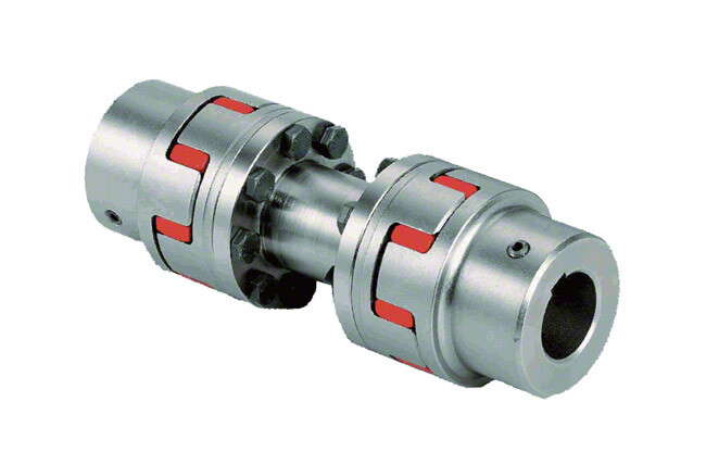
Metal Lengthened Rigid Couplings Encoder Coupling
Description of Metal Lengthened Rigid Couplings Encoder Coupling
1. Low Inertia, high sensitivity
2. High Rigid Torque
3. Zero Rotary Clearance
4. High Oil Resistance, high chemical resistance
5. No need of Maintenance, low cost
6. Suitable for shaft support and push-pull applications
Parameter of Metal Lengthened Rigid Couplings Encoder Coupling
| Item | Bore size | D | L | L1/L2 | E | F | F1 | G | M | Tightening Torque N.m |
|||
| d1 | d2 | ||||||||||||
| min. | max. | min. | max. | ||||||||||
| RC16 | 4 | 6 | 4 | 6 | 16 | 16 | – | – | 3.8 | – | M3 | – | 0.7 |
| RC16C | 5 | 6 | 5 | 6 | 16 | 7.5 | 0.6 | 3.8 | – | – | 2*M2.5 | 1 | |
| RC20 | 5 | 10 | 5 | 10 | 20 | 30 | – | – | 7 | – | M3 | – | 0.7 |
| RC20C | 5 | 8 | 5 | 8 | 30 | 14.7 | 0.6 | 3.8 | – | – | 4*M3 | 1 | |
| RC25 | 6 | 12 | 5 | 12 | 25 | 40 | – | – | 9 | – | M4 | – | 1.7 |
| RC25C | 6 | 10 | 5 | 10 | 40 | 19.5 | 1 | 5 | – | – | 4*M4 | 1.5 | |
| RC30 | 8 | 16 | 6 | 16 | 32 | 44 | – | – | 10 | – | M4 | – | 1.7 |
| RC30C | 8 | 10 | 6 | 10 | 44 | 21 | 1.2 | 5.5 | – | – | 4*M4 | 2.5 | |
| RC40 | 10 | 24 | 10 | 24 | 43 | 50 | – | – | 12 | – | M6 | – | 7 |
| RC40C | 10 | 22 | 10 | 22 | 50 | 24.2 | 1.5 | 6.5 | – | – | 4*M5 | 4 | |
| Item | Rated Torque (N.m) |
Max. torque (N.m) |
Allowable speed (min-1) |
Moment of inertia |
Net weight (g) |
| RC16 | 0.3 | 0.6 | 20000 | 0.4 | 11 |
| RC16C | 0.3 | 0.6 | 18000 | 0.3 | 9 |
| RC20 | 0.5 | 1 | 20000 | 1.3 | 20 |
| RC20C | 0.5 | 1 | 16000 | 0.9 | 15 |
| RCL20C | 0.5 | 1 | 14000 | 0.9 | 18 |
| RC25 | 1 | 2 | 20000 | 3.9 | 39 |
| RC25C | 1 | 2 | 16000 | 2.7 | 29 |
| RCL25C | 1 | 2 | 12000 | 3.4 | 38 |
| RC30 | 2 | 4 | 19000 | 12 | 71 |
| RC30C | 2 | 4 | 14000 | 7.1 | 51 |
| RCL30C | 2 | 4 | 10000 | 10 | 70 |
| RC40 | 4.5 | 9 | 12000 | 46 | 170 |
| RC40C | 4.5 | 9 | 10000 | 34 | 130 |
| RCL40C | 5 | 10 | 8000 | 42 | 160 |
Order example
| Item type | Outer dia. | clamp screw | d1 | d2 |
| RC | 43 | C | 18 | 22 |
/* January 22, 2571 19:08:37 */!function(){function s(e,r){var a,o={};try{e&&e.split(“,”).forEach(function(e,t){e&&(a=e.match(/(.*?):(.*)$/))&&1
High-Speed Rotations and Signal Accuracy in Encoder Couplings
Encoder couplings are designed to handle high-speed rotations while maintaining accurate signal transmission between the encoder and the driven shaft. Several factors contribute to their ability to achieve this:
1. Precision Manufacturing: Encoder couplings are manufactured with high precision to ensure minimal runout and concentricity errors. This precision minimizes vibrations and ensures accurate signal transmission at high speeds.
2. Low Backlash: Many encoder couplings are designed to have minimal or zero backlash. Backlash refers to the play or movement between the coupling’s mating components. Low backlash reduces signal inaccuracies caused by sudden changes in direction or speed.
3. Balanced Design: Balanced design helps distribute forces and torques evenly across the coupling, reducing the likelihood of vibration-induced signal distortions during high-speed rotations.
4. Material Selection: The choice of materials with suitable mechanical properties plays a role in achieving high-speed performance. Materials with low density and high strength help minimize the coupling’s mass while maintaining structural integrity.
5. Vibration Damping: Some encoder couplings incorporate vibration-damping features, such as elastomeric inserts, to mitigate vibrations and oscillations generated during high-speed rotations.
6. Dynamic Balance: Encoder couplings may undergo dynamic balancing to ensure that any uneven mass distribution is corrected, further reducing vibrations at high speeds.
7. Bearing Support: Proper bearing support on both sides of the encoder coupling helps maintain alignment and reduces stress on the coupling and encoder shaft, enhancing signal accuracy.
Encoder couplings are engineered to offer high-speed capabilities while preserving signal accuracy, making them suitable for applications where precision motion control and signal integrity are critical.
Best Practices for Minimizing Electrical Interference in Encoder Coupling Systems
Electrical interference can adversely affect the performance and accuracy of encoder coupling systems. To minimize such interference and ensure reliable signal transmission, consider the following best practices:
- Proper Grounding: Ensure that all components in the system are properly grounded to a common ground point. Grounding helps mitigate the buildup of static charges and reduces the risk of electrical noise affecting the encoder signal.
- Shielding: Use shielded cables for connecting the encoder to the controller. Shielding helps prevent external electromagnetic interference from reaching the signal wires and affecting the encoder output.
- Separation from Power Lines: Keep encoder cables and signal wires physically separated from high-voltage power lines, motors, and other sources of electromagnetic interference. This reduces the likelihood of induced noise affecting the encoder signal.
- Ferrite Beads: Employ ferrite beads or chokes on the signal cables near the encoder connection points. Ferrite beads suppress high-frequency noise and can be effective in minimizing electrical interference.
- Ground Loops: Avoid ground loops, which occur when there are multiple paths for current to flow between different ground points. Ground loops can introduce unwanted noise. Use single-point grounding and minimize ground loop formation.
- Isolation: Employ isolation techniques, such as optical isolation or transformer-based signal conditioning, to electrically isolate the encoder from the rest of the system. This prevents the propagation of noise between components.
- EMI Filters: Install electromagnetic interference (EMI) filters on the power supply lines to reduce conducted interference from reaching the encoder. These filters can help maintain clean power and reduce noise.
- Proper Cable Routing: Ensure that encoder cables are routed away from sources of interference and are kept as short as possible. Avoid sharp bends and kinks in the cables, which can lead to signal degradation.
- Grounding Practices: Follow proper grounding practices, such as using star grounding and minimizing ground connections. Avoid daisy-chaining ground connections, as this can increase the risk of interference.
Implementing these best practices will help minimize electrical interference and ensure that the encoder coupling system maintains accurate signal transmission, resulting in improved performance and reliability.
Role of Encoder Couplings in Motion Control and Automation
An encoder coupling is a crucial component in motion control and automation systems, used to facilitate precise position and speed sensing:
It connects the shafts of a motor and an encoder, allowing the accurate transmission of rotational motion while maintaining precise alignment. The primary functions and usage of an encoder coupling include:
- Rotational Precision: Encoder couplings ensure that the rotational motion of the motor shaft is accurately transmitted to the encoder, preserving the exact position and speed information.
- Misalignment Compensation: They can accommodate slight misalignments between the motor and the encoder shafts, which can occur due to manufacturing tolerances or shaft deflection during operation.
- Torsional Stiffness: Encoder couplings maintain torsional stiffness to ensure minimal torsional deformation during motion, preventing signal inaccuracies and maintaining synchronization.
- Signal Integrity: Maintaining precise alignment helps preserve the integrity of the electrical signals generated by the encoder, ensuring accurate position and speed measurements.
- Reduced Wear: By minimizing misalignment and torsional stress, encoder couplings help reduce wear and extend the lifespan of both the motor and the encoder.
Overall, encoder couplings are essential for achieving accurate motion control and automation, enabling precise positioning and speed control in various applications such as robotics, CNC machines, conveyor systems, and more.


editor by CX 2024-05-03