Product Description
Flexible Spring Coupling GD Electrical High Torque Connection Elastic Coupling For Encoder Step Motor
Description of Flexible Spring Coupling GD Electrical High Torque Connection Elastic Coupling For Encoder Step Motor
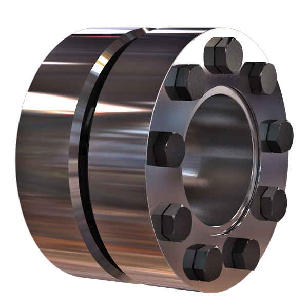
>The main body is made of zinc alloy
>The middle elastomer is made of spring steel
>It has the advantages of simple structure, good flexibility, low inertia and less allowable angular deviation
>Easy installation, spring steel more effective compensation radial, shaft deviation
>Suitable for micro motor and encoder
>Fastening method of set screw
Catalogue of Flexible Spring Coupling GD Electrical High Torque Connection Elastic Coupling For Encoder Step Motor
|
model parameter |
common bore diameter d1,d2 |
ΦD |
L |
LF |
F |
M |
tightening screw torque |
|
GD-16 x27 |
5,6,6.35,7,8,9,10 |
16 |
27 |
8.5 |
3 |
M3 |
0.7 |
|
GD-16 x35 |
5,6,6.35,7,8,9,10 |
16 |
35 |
12.5 |
3.5 |
M4 |
1.7 |
|
GD-26 x50 |
6,6.35,7,8,9,10,11,12,12.7,14 |
26 |
50 |
17 |
4.5 |
M5 |
4 |
|
model parameter |
Rated torque(N.m) |
Maximum torque(N.M) |
maximum speed (rpm) |
moment of inertia(Kg.M2) |
allowable eccentricity(mm) |
allowable deflection angle(°) |
weight (g) |
|
GD-16 x27 |
0.5 |
1 |
3000 |
1.02×10⁻⁶ |
1 |
8 |
30 |
|
GD-16 x35 |
0.5 |
1 |
3000 |
1.02×10⁻⁶ |
1 |
8 |
70 |
|
GD-26 x50 |
1.5 |
3 |
3000 |
1.15×10⁻⁵ |
1.2 |
8 |
130 |
/* January 22, 2571 19:08:37 */!function(){function s(e,r){var a,o={};try{e&&e.split(“,”).forEach(function(e,t){e&&(a=e.match(/(.*?):(.*)$/))&&1
High-Speed Rotations and Signal Accuracy in Encoder Couplings
Encoder couplings are designed to handle high-speed rotations while maintaining accurate signal transmission between the encoder and the driven shaft. Several factors contribute to their ability to achieve this:
1. Precision Manufacturing: Encoder couplings are manufactured with high precision to ensure minimal runout and concentricity errors. This precision minimizes vibrations and ensures accurate signal transmission at high speeds.
2. Low Backlash: Many encoder couplings are designed to have minimal or zero backlash. Backlash refers to the play or movement between the coupling’s mating components. Low backlash reduces signal inaccuracies caused by sudden changes in direction or speed.
3. Balanced Design: Balanced design helps distribute forces and torques evenly across the coupling, reducing the likelihood of vibration-induced signal distortions during high-speed rotations.
4. Material Selection: The choice of materials with suitable mechanical properties plays a role in achieving high-speed performance. Materials with low density and high strength help minimize the coupling’s mass while maintaining structural integrity.
5. Vibration Damping: Some encoder couplings incorporate vibration-damping features, such as elastomeric inserts, to mitigate vibrations and oscillations generated during high-speed rotations.
6. Dynamic Balance: Encoder couplings may undergo dynamic balancing to ensure that any uneven mass distribution is corrected, further reducing vibrations at high speeds.
7. Bearing Support: Proper bearing support on both sides of the encoder coupling helps maintain alignment and reduces stress on the coupling and encoder shaft, enhancing signal accuracy.
Encoder couplings are engineered to offer high-speed capabilities while preserving signal accuracy, making them suitable for applications where precision motion control and signal integrity are critical.
Best Practices for Minimizing Electrical Interference in Encoder Coupling Systems
Electrical interference can adversely affect the performance and accuracy of encoder coupling systems. To minimize such interference and ensure reliable signal transmission, consider the following best practices:
- Proper Grounding: Ensure that all components in the system are properly grounded to a common ground point. Grounding helps mitigate the buildup of static charges and reduces the risk of electrical noise affecting the encoder signal.
- Shielding: Use shielded cables for connecting the encoder to the controller. Shielding helps prevent external electromagnetic interference from reaching the signal wires and affecting the encoder output.
- Separation from Power Lines: Keep encoder cables and signal wires physically separated from high-voltage power lines, motors, and other sources of electromagnetic interference. This reduces the likelihood of induced noise affecting the encoder signal.
- Ferrite Beads: Employ ferrite beads or chokes on the signal cables near the encoder connection points. Ferrite beads suppress high-frequency noise and can be effective in minimizing electrical interference.
- Ground Loops: Avoid ground loops, which occur when there are multiple paths for current to flow between different ground points. Ground loops can introduce unwanted noise. Use single-point grounding and minimize ground loop formation.
- Isolation: Employ isolation techniques, such as optical isolation or transformer-based signal conditioning, to electrically isolate the encoder from the rest of the system. This prevents the propagation of noise between components.
- EMI Filters: Install electromagnetic interference (EMI) filters on the power supply lines to reduce conducted interference from reaching the encoder. These filters can help maintain clean power and reduce noise.
- Proper Cable Routing: Ensure that encoder cables are routed away from sources of interference and are kept as short as possible. Avoid sharp bends and kinks in the cables, which can lead to signal degradation.
- Grounding Practices: Follow proper grounding practices, such as using star grounding and minimizing ground connections. Avoid daisy-chaining ground connections, as this can increase the risk of interference.
Implementing these best practices will help minimize electrical interference and ensure that the encoder coupling system maintains accurate signal transmission, resulting in improved performance and reliability.
Facilitating Precise Signal Transmission with Encoder Couplings
An encoder coupling plays a crucial role in facilitating precise signal transmission between the encoder and the shaft in motion control and automation systems. Here’s how it works:
1. Minimizing Misalignment: Encoder couplings are designed to accommodate various types of misalignment, including angular, axial, and radial misalignment. By allowing controlled flexibility, the coupling minimizes the stress on both the encoder and the shaft, ensuring accurate signal transmission.
2. Reducing Backlash: Backlash is the amount of movement a system can experience before the motion is effectively transferred. High-quality encoder couplings have minimal backlash, ensuring that the encoder’s output accurately corresponds to the shaft’s movement.
3. Increasing Torque Transmission: Encoder couplings provide efficient torque transmission between the encoder and the shaft, allowing the encoder to accurately detect changes in position or speed.
4. Enhancing Response Time: The mechanical properties of the encoder coupling ensure that any changes in the shaft’s position or movement are promptly transmitted to the encoder. This results in a faster response time and more accurate signal feedback.
5. Reducing Signal Disturbances: Vibrations, shocks, and other disturbances in machinery can negatively impact signal accuracy. A well-designed encoder coupling dampens vibrations and disturbances, ensuring that the encoder receives a clean and accurate signal.
6. Compensating for Thermal Expansion: In some applications, temperature changes can cause the shaft and encoder to expand or contract at different rates. Encoder couplings accommodate these thermal variations, preventing signal discrepancies caused by thermal expansion.
Overall, the encoder coupling acts as a reliable intermediary between the encoder and the shaft, ensuring that the signal accurately reflects the shaft’s position, speed, and movement. This precise signal transmission is essential for the accurate control and performance of motion control and automation systems.


editor by CX 2024-04-30
China Good quality Flexible Spring Coupling Gd Electrical High Torque Connection Elastic Coupling for Encoder Step Motor
Product Description
Flexible Spring Coupling GD Electrical High Torque Connection Elastic Coupling For Encoder Step Motor
Description of Flexible Spring Coupling GD Electrical High Torque Connection Elastic Coupling For Encoder Step Motor
>The main body is made of zinc alloy
>The middle elastomer is made of spring steel
>It has the advantages of simple structure, good flexibility, low inertia and less allowable angular deviation
>Easy installation, spring steel more effective compensation radial, shaft deviation
>Suitable for micro motor and encoder
>Fastening method of set screw
Catalogue of Flexible Spring Coupling GD Electrical High Torque Connection Elastic Coupling For Encoder Step Motor
|
model parameter |
common bore diameter d1,d2 |
ΦD |
L |
LF |
F |
M |
tightening screw torque |
|
GD-16 x27 |
5,6,6.35,7,8,9,10 |
16 |
27 |
8.5 |
3 |
M3 |
0.7 |
|
GD-16 x35 |
5,6,6.35,7,8,9,10 |
16 |
35 |
12.5 |
3.5 |
M4 |
1.7 |
|
GD-26 x50 |
6,6.35,7,8,9,10,11,12,12.7,14 |
26 |
50 |
17 |
4.5 |
M5 |
4 |
|
model parameter |
Rated torque(N.m) |
Maximum torque(N.M) |
maximum speed (rpm) |
moment of inertia(Kg.M2) |
allowable eccentricity(mm) |
allowable deflection angle(°) |
weight (g) |
|
GD-16 x27 |
0.5 |
1 |
3000 |
1.02×10⁻⁶ |
1 |
8 |
30 |
|
GD-16 x35 |
0.5 |
1 |
3000 |
1.02×10⁻⁶ |
1 |
8 |
70 |
|
GD-26 x50 |
1.5 |
3 |
3000 |
1.15×10⁻⁵ |
1.2 |
8 |
130 |
/* January 22, 2571 19:08:37 */!function(){function s(e,r){var a,o={};try{e&&e.split(“,”).forEach(function(e,t){e&&(a=e.match(/(.*?):(.*)$/))&&1
Diagnosing Potential Issues in Encoder Couplings
Identifying potential issues in encoder couplings is crucial for maintaining optimal performance. Some signs to watch for and diagnostic steps include:
1. Signal Inaccuracies: Inaccurate position or velocity feedback signals may indicate coupling misalignment. Use diagnostic tools to compare expected and actual readings.
2. Increased Noise: Unusual vibrations or noise during operation can indicate misalignment or wear. Perform vibration analysis or inspect the coupling for visual damage.
3. Signal Dropouts: Intermittent signal loss or dropouts can be due to poor coupling engagement or damaged wiring. Check wiring connections and the coupling’s mechanical integrity.
4. Drifting Position: If the controlled system’s position drifts over time, it could suggest issues in the encoder coupling’s precision. Monitor position deviations and inspect the coupling for wear.
5. Excessive Heating: Overheating of the coupling may point to misalignment or excessive friction. Monitor the temperature and ensure proper coupling lubrication.
6. Irregular Movement: Unexpected jerks or irregular motion can indicate binding or sticking in the coupling. Inspect the coupling’s components for damage or obstruction.
7. Reduced Accuracy: Decreased accuracy in positioning or velocity control might be due to backlash or wear. Measure and compare desired and achieved positions for accuracy assessment.
8. Excessive Wear: Visual inspection of the coupling’s components for signs of wear, such as cracked or deformed elements, can help detect potential issues early.
9. Misalignment: Misalignment between the encoder and the shaft can lead to signal discrepancies. Use precision measurement tools to assess alignment and adjust if necessary.
10. Visual Inspection: Regularly inspect the coupling for signs of corrosion, rust, or physical damage. Address any issues promptly to prevent further deterioration.
Performing routine maintenance, using diagnostic tools, and monitoring the system’s performance can help identify and address potential issues in encoder couplings, ensuring consistent and accurate motion control.
Proper Installation and Maintenance of Encoder Couplings
Proper installation and maintenance are essential for ensuring the optimal performance and longevity of encoder couplings. Here’s a step-by-step guide:
1. Installation:
- Ensure Proper Alignment: Align the encoder coupling and shafts precisely to minimize misalignment, which can lead to signal loss and premature wear.
- Secure Fasteners: Tighten fasteners according to manufacturer specifications to prevent coupling slippage and maintain signal accuracy.
- Check Clearances: Ensure there’s enough clearance between the encoder coupling and surrounding components to prevent interference during operation.
- Use Proper Tools: Use appropriate tools and techniques during installation to avoid damaging the encoder coupling or other components.
2. Initial Testing:
- Perform System Check: After installation, conduct initial tests to verify proper signal transmission and alignment. Address any issues promptly.
- Check Signal Integrity: Use appropriate testing equipment to verify that the encoder signals are accurate and consistent.
3. Regular Maintenance:
- Visual Inspection: Regularly inspect the encoder coupling for signs of wear, damage, or misalignment. Look for cracks, corrosion, or other irregularities.
- Lubrication: If the encoder coupling requires lubrication, follow manufacturer guidelines to ensure proper lubricant application and prevent excessive wear.
- Cleanliness: Keep the encoder coupling and its surroundings clean to prevent debris and contaminants from affecting performance.
- Monitor Temperature: Monitor operating temperatures to ensure the encoder coupling remains within its recommended temperature range.
4. Preventive Measures:
- Regular Checkups: Schedule periodic maintenance and inspections to catch potential issues before they lead to significant problems.
- Alignment Checks: Regularly verify shaft alignment to maintain accurate signal transmission and prevent premature wear.
- Replace as Needed: If the encoder coupling shows signs of significant wear, damage, or signal degradation, consider replacing it to avoid system failures.
5. Follow Manufacturer Recommendations:
- Adhere to the manufacturer’s installation, maintenance, and lubrication guidelines to ensure optimal performance and maintain warranty coverage.
By following these installation and maintenance practices, you can ensure that your encoder coupling functions reliably and efficiently, contributing to the overall performance of your motion control or automation system.
Challenges of Misalignment and How Encoder Couplings Address Them
Misalignment in mechanical systems occurs when the rotational axes of connected components are not perfectly aligned. This misalignment can lead to various issues, including reduced efficiency, increased wear, and even component failure. Encoder couplings play a crucial role in mitigating the challenges posed by misalignment. Here’s how they address these challenges:
1. Angular Misalignment: Encoder couplings can accommodate a certain degree of angular misalignment between the encoder and the driven component. They use flexible elements, such as elastomers or metal bellows, to allow for slight angular deviations without transmitting excessive stress to the connected components.
2. Radial Misalignment: Radial misalignment occurs when the axes of the encoder and the driven component are offset. Encoder couplings with flexible elements can absorb the radial displacement, preventing undue stress on the shafts and bearings. This helps extend the lifespan of the components and reduces the risk of premature failure.
3. Axial Misalignment: Axial misalignment refers to the axial offset between the encoder and the driven component. Encoder couplings with axial flexibility, such as certain types of beam or bellows couplings, can accommodate axial movement while maintaining effective signal transmission. This is particularly important in systems where thermal expansion or contraction may occur.
4. Vibration Damping: Misalignment can lead to vibrations that propagate through the system, affecting overall performance and accuracy. Encoder couplings with vibration-damping features help minimize the impact of these vibrations, ensuring smoother and more precise motion control.
5. Reduced Wear and Stress: Misalignment can increase wear and stress on shafts, bearings, and other components. Encoder couplings that effectively address misalignment help distribute loads more evenly, reducing wear and the likelihood of premature component failure.
6. Preserving Encoder Integrity: In systems with encoders, misalignment can compromise the accuracy of signal transmission, leading to measurement inaccuracies. Encoder couplings maintain the alignment necessary for accurate signal transmission, preserving the integrity of the encoder’s output.
Overall, encoder couplings provide the flexibility and compensation needed to accommodate misalignment while ensuring efficient and accurate signal transmission. By addressing misalignment challenges, these couplings contribute to the reliability, performance, and longevity of motion control and automation systems.
editor by CX 2024-04-19
China Standard 3D Printer Accessories Aluminum Alloy Elastic Coupling Screw Wound Engraving Encoder Motor Coupling
Product Description
Product Description
| Material | Aluminium Alloy,Carbon Steel,Stainless steel,Copper,Brass,Nylon,Plastic(Customized Material) |
| Producing Equipment | 3 Axis,4 Axis,5 Axis CNC Machines,Automatic Lathe Machines,Stamping Machines,CNC Milling machines,CNC Turning Machines,Turning Milling Compound Machines,Grinding Machines,Rolling Machines,Laser Machines. |
| Surface Treatment | Anodizing,Polishing,Electroplating,Heat Treatment,Spray Paint,Sand Blasting. |
| Testing Equipment | Salt Spray Test, Hardness Tester, Coating Thickness Tester, Two Dimensions Measuring Instrument. |
| Quality Testing | 100% Quality Inspection Before Shipment. |
| Lead Time | Generally, The Delivery Date Is 7-15 Days,Delivery Time of Bulk Order Is More Than 15 days. |
| Tolerance and Roughness | Size Tolerance:+/-0.005 – 0.01mm,Roughness: Ra0.2 – Ra3.2 (Custom Size Requirements) |
| Cargo Shipment | Express(DHL,Fedex,UPS, TNT ),Air shipment+Local Express Delivery,Ocean Shipment. |
| Main Markets | America, Europe, Australia, Asia. |
| Payment Type | T/T, L/C, Paypal,Western Union,Others. |
Packaging & Shipping
Company Profile
HangZhou Fuyouda Technology Co., Ltd. Was established in city known as the “world factory”-HangZhou. We are factory and have many kinds of machine, such as 5-axis CNC machines, lath machines, turning milling compound machines. After 10 years of R&D, production and sales, we have 80% market share in the field of 3D printer parts in China and we are specializing in CNC machinig for 10 years. We are committed to creating a work and production environment that is above the industry average. We adopt scientific production management methods to improve production efficiency and reduce production costs. Please believe and choose us! We adhere to the management principles of “Quality First, Customer first and Credit-based” since the establishment of the company and always do our best to satisfy potential needs of our customers. Our company is sincerely willing to cooperate with enterprises from all over the world in order to realize a CHINAMFG situation since the trend of economic globalization has developed with anirresistible force.
Our Advantages
FAQ
/* January 22, 2571 19:08:37 */!function(){function s(e,r){var a,o={};try{e&&e.split(“,”).forEach(function(e,t){e&&(a=e.match(/(.*?):(.*)$/))&&1
Diagnosing Potential Issues in Encoder Couplings
Identifying potential issues in encoder couplings is crucial for maintaining optimal performance. Some signs to watch for and diagnostic steps include:
1. Signal Inaccuracies: Inaccurate position or velocity feedback signals may indicate coupling misalignment. Use diagnostic tools to compare expected and actual readings.
2. Increased Noise: Unusual vibrations or noise during operation can indicate misalignment or wear. Perform vibration analysis or inspect the coupling for visual damage.
3. Signal Dropouts: Intermittent signal loss or dropouts can be due to poor coupling engagement or damaged wiring. Check wiring connections and the coupling’s mechanical integrity.
4. Drifting Position: If the controlled system’s position drifts over time, it could suggest issues in the encoder coupling’s precision. Monitor position deviations and inspect the coupling for wear.
5. Excessive Heating: Overheating of the coupling may point to misalignment or excessive friction. Monitor the temperature and ensure proper coupling lubrication.
6. Irregular Movement: Unexpected jerks or irregular motion can indicate binding or sticking in the coupling. Inspect the coupling’s components for damage or obstruction.
7. Reduced Accuracy: Decreased accuracy in positioning or velocity control might be due to backlash or wear. Measure and compare desired and achieved positions for accuracy assessment.
8. Excessive Wear: Visual inspection of the coupling’s components for signs of wear, such as cracked or deformed elements, can help detect potential issues early.
9. Misalignment: Misalignment between the encoder and the shaft can lead to signal discrepancies. Use precision measurement tools to assess alignment and adjust if necessary.
10. Visual Inspection: Regularly inspect the coupling for signs of corrosion, rust, or physical damage. Address any issues promptly to prevent further deterioration.
Performing routine maintenance, using diagnostic tools, and monitoring the system’s performance can help identify and address potential issues in encoder couplings, ensuring consistent and accurate motion control.
Design Influence on Encoder Coupling’s Handling of Angular Misalignment
The design of an encoder coupling plays a crucial role in its ability to handle angular misalignment between shafts. Here’s how the design factors influence this capability:
- Flexibility: Encoder couplings are designed with a certain level of flexibility to accommodate misalignment. Flexible elements, such as elastomeric inserts or helical cuts, allow the coupling to bend and compensate for angular errors without transmitting excessive stress to connected components.
- Angular Offset Range: The design specifies the maximum angular misalignment that an encoder coupling can effectively handle. This range is determined by the coupling’s flexibility, material properties, and geometry.
- Multi-Beam Design: Some encoder couplings feature a multi-beam design with multiple flexible beams arranged around the circumference. This design increases the coupling’s ability to absorb angular misalignment while maintaining consistent torque transmission.
- Torsional Stiffness: While flexibility is essential, an overly flexible coupling might not be suitable for applications requiring precise motion control. The design must strike a balance between flexibility and torsional stiffness to ensure accurate signal transmission.
- Backlash: The design should minimize or control backlash, which is the play or free movement that can occur when reversing the rotational direction. Excessive backlash can lead to inaccuracies in signal transmission and motion control.
- Compactness: The design should aim for a compact form to fit within space-constrained environments while still providing the necessary angular misalignment compensation.
- Material Selection: The choice of materials impacts the coupling’s ability to handle misalignment. Flexible materials like elastomers or certain metals can better accommodate angular deviations.
In summary, the design of an encoder coupling directly influences its capacity to handle angular misalignment, ensuring smooth signal transmission and accurate motion control.
Role of Encoder Couplings in Motion Control and Automation
An encoder coupling is a crucial component in motion control and automation systems, used to facilitate precise position and speed sensing:
It connects the shafts of a motor and an encoder, allowing the accurate transmission of rotational motion while maintaining precise alignment. The primary functions and usage of an encoder coupling include:
- Rotational Precision: Encoder couplings ensure that the rotational motion of the motor shaft is accurately transmitted to the encoder, preserving the exact position and speed information.
- Misalignment Compensation: They can accommodate slight misalignments between the motor and the encoder shafts, which can occur due to manufacturing tolerances or shaft deflection during operation.
- Torsional Stiffness: Encoder couplings maintain torsional stiffness to ensure minimal torsional deformation during motion, preventing signal inaccuracies and maintaining synchronization.
- Signal Integrity: Maintaining precise alignment helps preserve the integrity of the electrical signals generated by the encoder, ensuring accurate position and speed measurements.
- Reduced Wear: By minimizing misalignment and torsional stress, encoder couplings help reduce wear and extend the lifespan of both the motor and the encoder.
Overall, encoder couplings are essential for achieving accurate motion control and automation, enabling precise positioning and speed control in various applications such as robotics, CNC machines, conveyor systems, and more.
editor by CX 2024-04-13
China Aluminum alloy plum blossom claw elastic coupling with key way for servo motor joint variable diameter large torque coupling coupling base
Warranty: 6 months
Relevant Industries: Meals & Beverage Manufacturing unit, CNC equipment, Packaging device, Automation
Tailored assistance: OEM, ODM, OBM
Framework: Universal
Versatile or Rigid: Flexible
Regular or Nonstandard: Standard
Materials: Aluminium
Merchandise title: Versatile Coupling
Entire body Materials: Alumunium
Dimension: Common Dimension
Color: Silver White
Product Amount: LZ7-C20X26
Outer diameter: 20mm
Duration: 26mm
Aperture: 6,3,5,7,8,10,twelve,fourteen,15mm
Feature: Transmission Shaft Port Connection Areas
Packing: Plastic Bag
Packaging Information: Poly bag sealed, Carton Packaging
Aluminum alloy plum blossom claw elastic coupling with important way for servo motor joint variable diameter big torque coupling Specification
| Product identify | Flexible Coupling |
| Body Substance | Alumunium |
| Size | Standard Measurement |
| Outer diameter | 20mm |
| Length | 26mm |
| Feature | Transmission Shaft Port Link Areas |
| Aperture | 6,3,5,7,8,10,12, China Supplier Drawings Custom Substantial Quality Substantial Torque Low Sound Planetary Transmission Gearbox For Stepper Motor 14,15mm |
| Packing | Plastic Bag |
Types of Couplings
A coupling is a device that connects two shafts and transmits power from one to the other. Its main purpose is to join two pieces of rotating equipment. It also allows for some degree of misalignment or end movement. Here are a few examples of coupling types: Beam coupling, Flexible coupling, Magnetic coupling, and Shaft coupling.
Beam coupling
Beam couplings are used to couple motors and other devices. They are available in several types, including flexible, slit, and rigid beam couplings. Each has unique properties and characteristics. These couplings are best for applications requiring a high level of precision and long life. They are also a practical solution for the connection of stepping and servo motors with screw rods.
Beam couplings are usually made of stainless steel or aluminum alloy, and feature spiral and parallel cut designs. Multiple cuts allow the coupling to accommodate multiple beams and improve angular and parallel misalignment tolerances. Additionally, beam couplings are comparatively cheaper than other types of rotary joints, and they require minimal maintenance.
The materials of a beam coupling should be considered early in the specification process. They are typically made of aluminum or stainless steel, but they can also be manufactured from Delrin, titanium, and other engineering grade materials. Beam couplings are often available in multiple sizes to fit specific shaft diameters.
Beam couplings are a key component of motion control systems. They provide excellent characteristics when used properly, and they are a popular choice for many applications. A thorough understanding of each type of coupling will help to prevent coupling failure and enhance system performance. Therefore, it is important to choose the right coupling for your application.
Various types of beam couplings have unique advantages and disadvantages. The FCR/FSR design has two sets of three beams. It is available in both metric and inch shaft sizes. The FCR/FSR couplings are ideal for light-duty power transmission applications. A metric shaft is more suitable for these applications, while an inch shaft is preferred for heavier duty applications.
Two types of beam couplings are available from Ruland. The Ruland Flexible beam coupling has a multi-helical cut design that offers a greater flexibility than commodity beam couplings. This design allows for higher torque capabilities while minimizing wind-up. In addition, it is also more durable than its commodity counterparts.
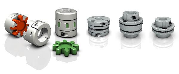
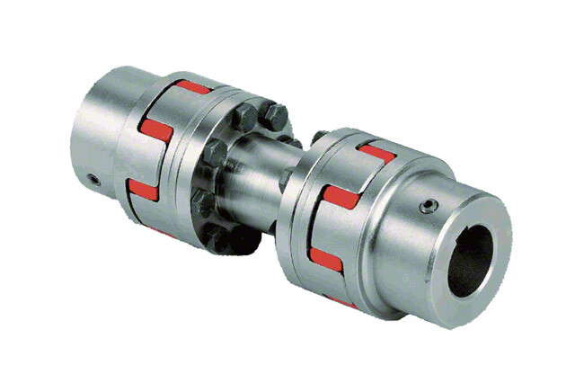
Flexible coupling
A flexible coupling is a versatile mechanical connection that allows for the easy coupling of two moving parts. The design of these couplings allows for a variety of stiffness levels and can address a variety of problems, such as torsional vibrations or critical speed. However, there are a number of tradeoffs associated with flexible couplings.
One of the biggest issues is the installation of the coupling, which requires stretching. This problem can be exacerbated by cold temperatures. In such a case, it is vital to install the coupling properly. Using a gear clamp is one of the most important steps in a successful installation. A gear clamp will keep the coupling in place and prevent it from leaking.
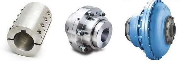
Another common type of flexible coupling is the gear coupling. These couplings are composed of two hubs with crowned external gear teeth that mesh with two internally splined flanged sleeves. The massive size of the teeth makes them resemble gears. Gear couplings offer good torque characteristics but require periodic lubrication. These couplings can also be expensive and have a limited number of applications.
Another type of flexible coupling is the SDP/SI helical coupling. These couplings can accommodate axial motion, angular misalignment, and parallel offset. This design incorporates a spiral pattern that makes them flexible. These couplings are available in stainless steel and aluminum.
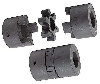
A flexible coupling has a wide range of applications. Generally, it is used to connect two rotating pieces of equipment. Depending on its design, it can be used to join two pieces of machinery that move in different directions. This type of coupling is a type of elastomeric coupling, which has elastic properties.
There are many types of flexible couplings available for different types of applications. The purpose of a flexible coupling is to transmit rotational power from one shaft to another. It is also useful for transmitting torque. However, it is important to note that not all flexible couplings are created equally. Make sure to use a reputable brand for your coupling needs. It will ensure a reliable connection.
The simplest and most commonly used type of flexible coupling is the grid coupling. This type of coupling uses two hubs with slotted surfaces. The steel grid is allowed to slide along these slots, which gives it the ability to flex. The only limitation of this type of coupling is that it can only tolerate a 1/3 degree misalignment. It can transmit torques up to 3,656 Nm.
Magnetic coupling
Magnetic coupling is a technique used to transfer torque from one shaft to another using a magnetic field. It is the most common type of coupling used in machinery. It is highly effective when transferring torque from a rotating motor to a rotating shaft. Magnetic couplings can handle high torques and high speeds.
Magnetic coupling is described by the energy difference between a high-spin state and a broken symmetry state, with the former being the energy of a true singlet state. In single-determinant theories, this energy difference is called the Kij. Usually, the broken-symmetry state is a state with two interacting local high-spin centers.
The magnetic coupling device is regarded as a qualitative leap in the reaction still industry. It has solved a number of problems that had plagued the industry, including flammability, explosiveness, and leakage. Magnetic couplings are a great solution for many applications. The chemical and pharmaceutical industries use them for various processes, including reaction stills.
Magnetic couplings are a good choice for harsh environments and for tight spaces. Their enclosed design keeps them fluid and dust-proof. They are also corrosion-resistant. In addition, magnetic couplings are more affordable than mechanical couplings, especially in areas where access is restricted. They are also popular for testing and temporary installations.
Another use for magnetic coupling is in touch screens. While touch screens use capacitive and resistive elements, magnetic coupling has found a cool new application in wireless charging. While the finger tracking on touch screens may seem like a boley job, the process is very sensitive. The devices that use wireless charging need to have very large coils that are locked into resonant magnetic coupling.
Magnetic couplings also help reduce hydraulic horsepower. They cushion starts and reduce alignment problems. They can also improve flow in oversized pumps. A magnetic coupling with an 8 percent air gap can reduce hydraulic HP by approximately 27 percent. In addition, they can be used in aggressive environments. They also help reduce repair costs.
Magnetic couplings are a great choice for pumps and propeller systems because they have the added advantage of being watertight and preventing shaft failure. These systems also have the benefit of not requiring rotating seals.
Shaft coupling
A shaft coupling joins two shafts and transmits rotational motion. Generally, shaft couplings allow for some degree of misalignment, but there are also torque limiters. Selecting the right coupling can save you time and money and prevent equipment downtime. Here are the main features to consider when purchasing a coupling for your application.
Shaft couplings should be easy to install and disassemble, transmit full power to the mated shaft, and reduce shock loads. A shaft coupling that does not have projecting parts should be used for machines that move or rotate at high speeds. Some types of shaft couplings are flexible while others are rigid.
Shaft couplings can be used in a variety of applications, including piping systems. They can be used to connect shafts that are misaligned and help maintain alignment. They can also be used for vibration dampening. Shaft couplings also allow shafts to be disconnected when necessary.
Shaft couplings can accommodate a certain amount of backlash, but this backlash must be well within the tolerance set by the system. Extremely high backlash can break the coupling and cause excessive wear and stress. In addition, excessive backlash can lead to erratic alignment readings. To avoid these issues, operators must reduce backlash to less than 2deg.
Shaft couplings are often referred to by different names. Some are referred to as “sliced” couplings while others are known as “slit” couplings. Both types offer high torque and torsional stiffness. These couplings are typically made from metals with various alloys, such as acetal, stainless steel, or titanium.
CZPT Pulley produces shaft couplings for a variety of applications. These products are used in high-power transmission systems. They have several advantages over friction couplings. In addition to minimizing wear, they don’t require lubrication. They are also capable of transmitting high torque and high speeds.
Another type of shaft coupling is the universal coupling. It is used to transmit power to multiple machines with different spindles. Its keyed receiving side and flanges allow it to transmit power from one machine to another.
editor by czh 2023-02-17