Product Description
Flexible Spring Coupling GD Electrical High Torque Connection Elastic Coupling For Encoder Step Motor
Description of Flexible Spring Coupling GD Electrical High Torque Connection Elastic Coupling For Encoder Step Motor
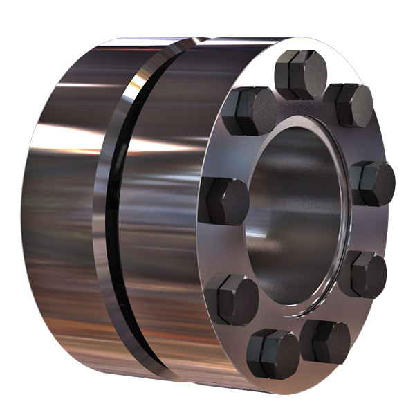
>The main body is made of zinc alloy
>The middle elastomer is made of spring steel
>It has the advantages of simple structure, good flexibility, low inertia and less allowable angular deviation
>Easy installation, spring steel more effective compensation radial, shaft deviation
>Suitable for micro motor and encoder
>Fastening method of set screw
Catalogue of Flexible Spring Coupling GD Electrical High Torque Connection Elastic Coupling For Encoder Step Motor
|
model parameter |
common bore diameter d1,d2 |
ΦD |
L |
LF |
F |
M |
tightening screw torque |
|
GD-16 x27 |
5,6,6.35,7,8,9,10 |
16 |
27 |
8.5 |
3 |
M3 |
0.7 |
|
GD-16 x35 |
5,6,6.35,7,8,9,10 |
16 |
35 |
12.5 |
3.5 |
M4 |
1.7 |
|
GD-26 x50 |
6,6.35,7,8,9,10,11,12,12.7,14 |
26 |
50 |
17 |
4.5 |
M5 |
4 |
|
model parameter |
Rated torque(N.m) |
Maximum torque(N.M) |
maximum speed (rpm) |
moment of inertia(Kg.M2) |
allowable eccentricity(mm) |
allowable deflection angle(°) |
weight (g) |
|
GD-16 x27 |
0.5 |
1 |
3000 |
1.02×10⁻⁶ |
1 |
8 |
30 |
|
GD-16 x35 |
0.5 |
1 |
3000 |
1.02×10⁻⁶ |
1 |
8 |
70 |
|
GD-26 x50 |
1.5 |
3 |
3000 |
1.15×10⁻⁵ |
1.2 |
8 |
130 |
/* January 22, 2571 19:08:37 */!function(){function s(e,r){var a,o={};try{e&&e.split(“,”).forEach(function(e,t){e&&(a=e.match(/(.*?):(.*)$/))&&1
High-Speed Rotations and Signal Accuracy in Encoder Couplings
Encoder couplings are designed to handle high-speed rotations while maintaining accurate signal transmission between the encoder and the driven shaft. Several factors contribute to their ability to achieve this:
1. Precision Manufacturing: Encoder couplings are manufactured with high precision to ensure minimal runout and concentricity errors. This precision minimizes vibrations and ensures accurate signal transmission at high speeds.
2. Low Backlash: Many encoder couplings are designed to have minimal or zero backlash. Backlash refers to the play or movement between the coupling’s mating components. Low backlash reduces signal inaccuracies caused by sudden changes in direction or speed.
3. Balanced Design: Balanced design helps distribute forces and torques evenly across the coupling, reducing the likelihood of vibration-induced signal distortions during high-speed rotations.
4. Material Selection: The choice of materials with suitable mechanical properties plays a role in achieving high-speed performance. Materials with low density and high strength help minimize the coupling’s mass while maintaining structural integrity.
5. Vibration Damping: Some encoder couplings incorporate vibration-damping features, such as elastomeric inserts, to mitigate vibrations and oscillations generated during high-speed rotations.
6. Dynamic Balance: Encoder couplings may undergo dynamic balancing to ensure that any uneven mass distribution is corrected, further reducing vibrations at high speeds.
7. Bearing Support: Proper bearing support on both sides of the encoder coupling helps maintain alignment and reduces stress on the coupling and encoder shaft, enhancing signal accuracy.
Encoder couplings are engineered to offer high-speed capabilities while preserving signal accuracy, making them suitable for applications where precision motion control and signal integrity are critical.
Best Practices for Minimizing Electrical Interference in Encoder Coupling Systems
Electrical interference can adversely affect the performance and accuracy of encoder coupling systems. To minimize such interference and ensure reliable signal transmission, consider the following best practices:
- Proper Grounding: Ensure that all components in the system are properly grounded to a common ground point. Grounding helps mitigate the buildup of static charges and reduces the risk of electrical noise affecting the encoder signal.
- Shielding: Use shielded cables for connecting the encoder to the controller. Shielding helps prevent external electromagnetic interference from reaching the signal wires and affecting the encoder output.
- Separation from Power Lines: Keep encoder cables and signal wires physically separated from high-voltage power lines, motors, and other sources of electromagnetic interference. This reduces the likelihood of induced noise affecting the encoder signal.
- Ferrite Beads: Employ ferrite beads or chokes on the signal cables near the encoder connection points. Ferrite beads suppress high-frequency noise and can be effective in minimizing electrical interference.
- Ground Loops: Avoid ground loops, which occur when there are multiple paths for current to flow between different ground points. Ground loops can introduce unwanted noise. Use single-point grounding and minimize ground loop formation.
- Isolation: Employ isolation techniques, such as optical isolation or transformer-based signal conditioning, to electrically isolate the encoder from the rest of the system. This prevents the propagation of noise between components.
- EMI Filters: Install electromagnetic interference (EMI) filters on the power supply lines to reduce conducted interference from reaching the encoder. These filters can help maintain clean power and reduce noise.
- Proper Cable Routing: Ensure that encoder cables are routed away from sources of interference and are kept as short as possible. Avoid sharp bends and kinks in the cables, which can lead to signal degradation.
- Grounding Practices: Follow proper grounding practices, such as using star grounding and minimizing ground connections. Avoid daisy-chaining ground connections, as this can increase the risk of interference.
Implementing these best practices will help minimize electrical interference and ensure that the encoder coupling system maintains accurate signal transmission, resulting in improved performance and reliability.
Facilitating Precise Signal Transmission with Encoder Couplings
An encoder coupling plays a crucial role in facilitating precise signal transmission between the encoder and the shaft in motion control and automation systems. Here’s how it works:
1. Minimizing Misalignment: Encoder couplings are designed to accommodate various types of misalignment, including angular, axial, and radial misalignment. By allowing controlled flexibility, the coupling minimizes the stress on both the encoder and the shaft, ensuring accurate signal transmission.
2. Reducing Backlash: Backlash is the amount of movement a system can experience before the motion is effectively transferred. High-quality encoder couplings have minimal backlash, ensuring that the encoder’s output accurately corresponds to the shaft’s movement.
3. Increasing Torque Transmission: Encoder couplings provide efficient torque transmission between the encoder and the shaft, allowing the encoder to accurately detect changes in position or speed.
4. Enhancing Response Time: The mechanical properties of the encoder coupling ensure that any changes in the shaft’s position or movement are promptly transmitted to the encoder. This results in a faster response time and more accurate signal feedback.
5. Reducing Signal Disturbances: Vibrations, shocks, and other disturbances in machinery can negatively impact signal accuracy. A well-designed encoder coupling dampens vibrations and disturbances, ensuring that the encoder receives a clean and accurate signal.
6. Compensating for Thermal Expansion: In some applications, temperature changes can cause the shaft and encoder to expand or contract at different rates. Encoder couplings accommodate these thermal variations, preventing signal discrepancies caused by thermal expansion.
Overall, the encoder coupling acts as a reliable intermediary between the encoder and the shaft, ensuring that the signal accurately reflects the shaft’s position, speed, and movement. This precise signal transmission is essential for the accurate control and performance of motion control and automation systems.


editor by CX 2024-04-30
China Good quality Flexible Spring Coupling Gd Electrical High Torque Connection Elastic Coupling for Encoder Step Motor
Product Description
Flexible Spring Coupling GD Electrical High Torque Connection Elastic Coupling For Encoder Step Motor
Description of Flexible Spring Coupling GD Electrical High Torque Connection Elastic Coupling For Encoder Step Motor
>The main body is made of zinc alloy
>The middle elastomer is made of spring steel
>It has the advantages of simple structure, good flexibility, low inertia and less allowable angular deviation
>Easy installation, spring steel more effective compensation radial, shaft deviation
>Suitable for micro motor and encoder
>Fastening method of set screw
Catalogue of Flexible Spring Coupling GD Electrical High Torque Connection Elastic Coupling For Encoder Step Motor
|
model parameter |
common bore diameter d1,d2 |
ΦD |
L |
LF |
F |
M |
tightening screw torque |
|
GD-16 x27 |
5,6,6.35,7,8,9,10 |
16 |
27 |
8.5 |
3 |
M3 |
0.7 |
|
GD-16 x35 |
5,6,6.35,7,8,9,10 |
16 |
35 |
12.5 |
3.5 |
M4 |
1.7 |
|
GD-26 x50 |
6,6.35,7,8,9,10,11,12,12.7,14 |
26 |
50 |
17 |
4.5 |
M5 |
4 |
|
model parameter |
Rated torque(N.m) |
Maximum torque(N.M) |
maximum speed (rpm) |
moment of inertia(Kg.M2) |
allowable eccentricity(mm) |
allowable deflection angle(°) |
weight (g) |
|
GD-16 x27 |
0.5 |
1 |
3000 |
1.02×10⁻⁶ |
1 |
8 |
30 |
|
GD-16 x35 |
0.5 |
1 |
3000 |
1.02×10⁻⁶ |
1 |
8 |
70 |
|
GD-26 x50 |
1.5 |
3 |
3000 |
1.15×10⁻⁵ |
1.2 |
8 |
130 |
/* January 22, 2571 19:08:37 */!function(){function s(e,r){var a,o={};try{e&&e.split(“,”).forEach(function(e,t){e&&(a=e.match(/(.*?):(.*)$/))&&1
Diagnosing Potential Issues in Encoder Couplings
Identifying potential issues in encoder couplings is crucial for maintaining optimal performance. Some signs to watch for and diagnostic steps include:
1. Signal Inaccuracies: Inaccurate position or velocity feedback signals may indicate coupling misalignment. Use diagnostic tools to compare expected and actual readings.
2. Increased Noise: Unusual vibrations or noise during operation can indicate misalignment or wear. Perform vibration analysis or inspect the coupling for visual damage.
3. Signal Dropouts: Intermittent signal loss or dropouts can be due to poor coupling engagement or damaged wiring. Check wiring connections and the coupling’s mechanical integrity.
4. Drifting Position: If the controlled system’s position drifts over time, it could suggest issues in the encoder coupling’s precision. Monitor position deviations and inspect the coupling for wear.
5. Excessive Heating: Overheating of the coupling may point to misalignment or excessive friction. Monitor the temperature and ensure proper coupling lubrication.
6. Irregular Movement: Unexpected jerks or irregular motion can indicate binding or sticking in the coupling. Inspect the coupling’s components for damage or obstruction.
7. Reduced Accuracy: Decreased accuracy in positioning or velocity control might be due to backlash or wear. Measure and compare desired and achieved positions for accuracy assessment.
8. Excessive Wear: Visual inspection of the coupling’s components for signs of wear, such as cracked or deformed elements, can help detect potential issues early.
9. Misalignment: Misalignment between the encoder and the shaft can lead to signal discrepancies. Use precision measurement tools to assess alignment and adjust if necessary.
10. Visual Inspection: Regularly inspect the coupling for signs of corrosion, rust, or physical damage. Address any issues promptly to prevent further deterioration.
Performing routine maintenance, using diagnostic tools, and monitoring the system’s performance can help identify and address potential issues in encoder couplings, ensuring consistent and accurate motion control.
Proper Installation and Maintenance of Encoder Couplings
Proper installation and maintenance are essential for ensuring the optimal performance and longevity of encoder couplings. Here’s a step-by-step guide:
1. Installation:
- Ensure Proper Alignment: Align the encoder coupling and shafts precisely to minimize misalignment, which can lead to signal loss and premature wear.
- Secure Fasteners: Tighten fasteners according to manufacturer specifications to prevent coupling slippage and maintain signal accuracy.
- Check Clearances: Ensure there’s enough clearance between the encoder coupling and surrounding components to prevent interference during operation.
- Use Proper Tools: Use appropriate tools and techniques during installation to avoid damaging the encoder coupling or other components.
2. Initial Testing:
- Perform System Check: After installation, conduct initial tests to verify proper signal transmission and alignment. Address any issues promptly.
- Check Signal Integrity: Use appropriate testing equipment to verify that the encoder signals are accurate and consistent.
3. Regular Maintenance:
- Visual Inspection: Regularly inspect the encoder coupling for signs of wear, damage, or misalignment. Look for cracks, corrosion, or other irregularities.
- Lubrication: If the encoder coupling requires lubrication, follow manufacturer guidelines to ensure proper lubricant application and prevent excessive wear.
- Cleanliness: Keep the encoder coupling and its surroundings clean to prevent debris and contaminants from affecting performance.
- Monitor Temperature: Monitor operating temperatures to ensure the encoder coupling remains within its recommended temperature range.
4. Preventive Measures:
- Regular Checkups: Schedule periodic maintenance and inspections to catch potential issues before they lead to significant problems.
- Alignment Checks: Regularly verify shaft alignment to maintain accurate signal transmission and prevent premature wear.
- Replace as Needed: If the encoder coupling shows signs of significant wear, damage, or signal degradation, consider replacing it to avoid system failures.
5. Follow Manufacturer Recommendations:
- Adhere to the manufacturer’s installation, maintenance, and lubrication guidelines to ensure optimal performance and maintain warranty coverage.
By following these installation and maintenance practices, you can ensure that your encoder coupling functions reliably and efficiently, contributing to the overall performance of your motion control or automation system.
Challenges of Misalignment and How Encoder Couplings Address Them
Misalignment in mechanical systems occurs when the rotational axes of connected components are not perfectly aligned. This misalignment can lead to various issues, including reduced efficiency, increased wear, and even component failure. Encoder couplings play a crucial role in mitigating the challenges posed by misalignment. Here’s how they address these challenges:
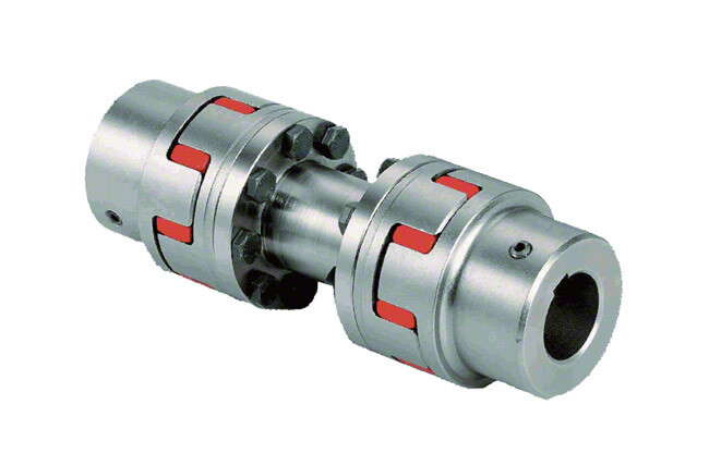
1. Angular Misalignment: Encoder couplings can accommodate a certain degree of angular misalignment between the encoder and the driven component. They use flexible elements, such as elastomers or metal bellows, to allow for slight angular deviations without transmitting excessive stress to the connected components.
2. Radial Misalignment: Radial misalignment occurs when the axes of the encoder and the driven component are offset. Encoder couplings with flexible elements can absorb the radial displacement, preventing undue stress on the shafts and bearings. This helps extend the lifespan of the components and reduces the risk of premature failure.
3. Axial Misalignment: Axial misalignment refers to the axial offset between the encoder and the driven component. Encoder couplings with axial flexibility, such as certain types of beam or bellows couplings, can accommodate axial movement while maintaining effective signal transmission. This is particularly important in systems where thermal expansion or contraction may occur.
4. Vibration Damping: Misalignment can lead to vibrations that propagate through the system, affecting overall performance and accuracy. Encoder couplings with vibration-damping features help minimize the impact of these vibrations, ensuring smoother and more precise motion control.
5. Reduced Wear and Stress: Misalignment can increase wear and stress on shafts, bearings, and other components. Encoder couplings that effectively address misalignment help distribute loads more evenly, reducing wear and the likelihood of premature component failure.
6. Preserving Encoder Integrity: In systems with encoders, misalignment can compromise the accuracy of signal transmission, leading to measurement inaccuracies. Encoder couplings maintain the alignment necessary for accurate signal transmission, preserving the integrity of the encoder’s output.
Overall, encoder couplings provide the flexibility and compensation needed to accommodate misalignment while ensuring efficient and accurate signal transmission. By addressing misalignment challenges, these couplings contribute to the reliability, performance, and longevity of motion control and automation systems.
editor by CX 2024-04-19
China Professional High Torque Motor Generator Shaft Type Flexible Clamp Metal Bellows Couplings
Product Description
|
Product Name |
High Torque Motor Generator Shaft Type Flexible Clamp Metal Bellows Couplings |
|
Material |
Aluminum alloy |
|
Surface treatment |
Natural color anode |
|
Customized service |
Support light customization and logo customization |
|
Remarks |
The default engraving brand name and size of the product. If you need not engraving, please contact the customer service for comments |
| Packaging Details | Carton box with anti-static package,carton plus with wooden case. |
| Main Products | Shaft Parts, Timing Belt Pulley, Gears, CNC Machining Parts, Sheet Metal Fabrication |
| Certifications(2) | ISO9001:2015, IPMS |
| Applicable Industries | Building Material Shops, Manufacturing Plant, Food & Beverage Factory, Farms |
| Supply Ability | 100000 Piece/Pieces per Month |
| Dimension | oem provided |
| Surface finish | anodized |
| Lead Time | 25 days |
| Application | Furniture,cabinet |
| Custom | OEM and ODM services are welcome,we can make cutom LOGO and products according to customer’s requests. |
| Quality control Our | Finished product inspection,Warranty available |
| service | Swiss machining;deburring;lathe/turning;5 axis;micromachining |
| Color |
silver,gold,black,red,bulue,and according to the customer requests. |
/* January 22, 2571 19:08:37 */!function(){function s(e,r){var a,o={};try{e&&e.split(“,”).forEach(function(e,t){e&&(a=e.match(/(.*?):(.*)$/))&&1
Materials Used in Manufacturing Encoder Couplings
Encoder couplings are manufactured using a variety of materials, each chosen for its specific properties and suitability for the intended application. Commonly used materials include:
1. Aluminum: Aluminum is lightweight, corrosion-resistant, and offers good machinability. It is often used for encoder couplings in applications where weight reduction and moderate torque transmission are important.
2. Stainless Steel: Stainless steel is known for its excellent corrosion resistance and durability. It is commonly used in environments where exposure to moisture, chemicals, or harsh conditions is a concern.
3. Steel: Steel is robust and offers high strength, making it suitable for heavy-duty applications with higher torque requirements. It can be further treated for enhanced corrosion resistance.
4. Brass: Brass provides good corrosion resistance and electrical conductivity. It is often used in applications where electrical isolation between components is necessary.
5. Plastics: Various engineering plastics such as nylon, polyurethane, and PEEK (polyether ether ketone) are used in encoder couplings. These materials offer good wear resistance, low friction, and electrical insulation.
6. Carbon Fiber: Carbon fiber is a lightweight, high-strength material known for its exceptional stiffness-to-weight ratio. It is used in applications where minimizing weight while maintaining rigidity is crucial.
7. Composite Materials: Composite materials combine different materials to achieve specific properties. They can offer a combination of strength, rigidity, and lightweight characteristics.
The choice of material depends on factors such as the application’s requirements, environmental conditions, torque and speed specifications, and the need for electrical insulation or conductivity. When selecting the material for an encoder coupling, it’s essential to consider the mechanical, thermal, and chemical properties required for optimal performance and longevity.
Impact of Encoder Resolution on Choice of Coupling
The encoder resolution plays a crucial role in selecting an appropriate coupling for your system. Encoder resolution refers to the number of distinct positions a rotary encoder can detect in one full rotation. Here’s how encoder resolution impacts the choice of coupling:
1. Precision Requirements:
Higher encoder resolutions provide finer position accuracy. If your application demands high precision and accuracy, such as in robotics or CNC machines, a coupling that minimizes backlash and offers precise torque transmission is essential.
2. Backlash Sensitivity:
As encoder resolution increases, the system becomes more sensitive to backlash (play between coupling components). To mitigate this, a coupling with minimal backlash, such as a zero-backlash or low-backlash coupling, is recommended to ensure accurate position feedback.
3. Dynamic Response:
Higher encoder resolutions allow systems to detect even small movements, improving dynamic response. For applications requiring rapid and accurate positioning changes, a coupling that provides high torsional stiffness and low wind-up is beneficial.
4. Mechanical Compliance:
Low-resolution encoders may tolerate some misalignment due to their coarser feedback intervals. However, high-resolution encoders are more sensitive to misalignment, making it important to choose a coupling that accommodates misalignment while maintaining signal accuracy.
5. Coupling Selection:
For high-resolution encoders, consider couplings that provide precision, low backlash, and accurate torque transmission, such as beam couplings, bellows couplings, or Oldham couplings. These couplings help maintain the integrity of position feedback and optimize system performance.
6. Environmental Factors:
The operating environment can affect the choice of coupling. For applications with extreme conditions, such as temperature fluctuations or aggressive chemicals, select a coupling material that can withstand these conditions without compromising the encoder’s accuracy.
Ultimately, the encoder resolution influences the coupling choice by demanding a coupling that complements the precision, accuracy, and dynamic performance required by the application.
Role of Encoder Couplings in Motion Control and Automation
An encoder coupling is a crucial component in motion control and automation systems, used to facilitate precise position and speed sensing:
It connects the shafts of a motor and an encoder, allowing the accurate transmission of rotational motion while maintaining precise alignment. The primary functions and usage of an encoder coupling include:
- Rotational Precision: Encoder couplings ensure that the rotational motion of the motor shaft is accurately transmitted to the encoder, preserving the exact position and speed information.
- Misalignment Compensation: They can accommodate slight misalignments between the motor and the encoder shafts, which can occur due to manufacturing tolerances or shaft deflection during operation.
- Torsional Stiffness: Encoder couplings maintain torsional stiffness to ensure minimal torsional deformation during motion, preventing signal inaccuracies and maintaining synchronization.
- Signal Integrity: Maintaining precise alignment helps preserve the integrity of the electrical signals generated by the encoder, ensuring accurate position and speed measurements.
- Reduced Wear: By minimizing misalignment and torsional stress, encoder couplings help reduce wear and extend the lifespan of both the motor and the encoder.
Overall, encoder couplings are essential for achieving accurate motion control and automation, enabling precise positioning and speed control in various applications such as robotics, CNC machines, conveyor systems, and more.
editor by CX 2024-03-11
China Professional High Torque Motor Generator Shaft Type Flexible Clamp Metal Bellows Couplings
Product Description
| ProductName | High Torque Motor Generator Shaft Type bellows flexible coupling clamp Metal Bellows Couplings For Power Transmission |
|
Bushings |
7075 Aluminum Alloy |
|
Corrugated Pipe |
301 Stainless steel |
|
Clamping Screw |
12.9 Level |
|
Size of Coupling |
Stardand, Unstardand Size Customized Available |
|
Types |
Clamping + Top Wire |
|
Keyway |
Stardand, Unstardand Size Customized Available |
|
Size of Inner Hole |
High Precision H7 standard |
|
Surface Treatment |
Oxidation and Not Oxidized (If there is no note, it will be shipped randomly.) |
Diagnosing Potential Issues in Encoder Couplings
Identifying potential issues in encoder couplings is crucial for maintaining optimal performance. Some signs to watch for and diagnostic steps include:
1. Signal Inaccuracies: Inaccurate position or velocity feedback signals may indicate coupling misalignment. Use diagnostic tools to compare expected and actual readings.
2. Increased Noise: Unusual vibrations or noise during operation can indicate misalignment or wear. Perform vibration analysis or inspect the coupling for visual damage.
3. Signal Dropouts: Intermittent signal loss or dropouts can be due to poor coupling engagement or damaged wiring. Check wiring connections and the coupling’s mechanical integrity.
4. Drifting Position: If the controlled system’s position drifts over time, it could suggest issues in the encoder coupling’s precision. Monitor position deviations and inspect the coupling for wear.
5. Excessive Heating: Overheating of the coupling may point to misalignment or excessive friction. Monitor the temperature and ensure proper coupling lubrication.
6. Irregular Movement: Unexpected jerks or irregular motion can indicate binding or sticking in the coupling. Inspect the coupling’s components for damage or obstruction.
7. Reduced Accuracy: Decreased accuracy in positioning or velocity control might be due to backlash or wear. Measure and compare desired and achieved positions for accuracy assessment.
8. Excessive Wear: Visual inspection of the coupling’s components for signs of wear, such as cracked or deformed elements, can help detect potential issues early.
9. Misalignment: Misalignment between the encoder and the shaft can lead to signal discrepancies. Use precision measurement tools to assess alignment and adjust if necessary.
10. Visual Inspection: Regularly inspect the coupling for signs of corrosion, rust, or physical damage. Address any issues promptly to prevent further deterioration.
Performing routine maintenance, using diagnostic tools, and monitoring the system’s performance can help identify and address potential issues in encoder couplings, ensuring consistent and accurate motion control.
Enhancing Accuracy and Reliability of Position and Velocity Measurements with Encoder Couplings
Yes, encoder couplings play a significant role in enhancing the accuracy and reliability of position and velocity measurements in various applications. Here’s how they contribute:
- Direct Signal Transmission: Encoder couplings directly connect the encoder to the shaft, ensuring that the rotational position and velocity information is accurately transmitted without delays or signal degradation.
- Minimized Signal Interference: Encoder couplings are designed to minimize electrical interference and noise, which could otherwise affect the accuracy of signal readings. This leads to more precise measurements of position and velocity.
- Backlash Reduction: Encoder couplings with low backlash ensure that any reversals in direction are accurately captured, resulting in improved accuracy in both position and velocity measurements.
- Elimination of Misalignment Errors: By compensating for angular misalignment between shafts, encoder couplings eliminate errors caused by misalignment, ensuring that the measured position and velocity data correspond accurately to the actual motion.
- Consistent Signal Quality: Encoder couplings maintain a consistent signal quality even in dynamic conditions, such as rapid changes in direction or speed. This consistency leads to reliable and accurate measurements.
- High Precision Applications: In applications requiring high precision, such as robotics, CNC machinery, or scientific instruments, encoder couplings ensure that even minor discrepancies in position and velocity are minimized.
- Long-Term Stability: Encoder couplings provide stable and repeatable measurements over time, ensuring that the accuracy and reliability of position and velocity data are maintained throughout the equipment’s lifespan.
In conclusion, encoder couplings significantly enhance the accuracy and reliability of position and velocity measurements by directly transmitting signals, reducing interference, compensating for misalignment, and providing consistent signal quality.
Importance of Backlash Reduction in Encoder Couplings
Backlash reduction is a critical consideration when selecting encoder couplings, particularly in motion control and automation applications that require precision and accuracy. Backlash refers to the angular or linear movement that occurs when the direction of motion changes in a mechanical system.
In encoder couplings, backlash can lead to inaccuracies in signal transmission between the encoder and the driven component. This is especially problematic in applications that involve rapid changes in direction or require precise positioning. The importance of backlash reduction can be understood through the following points:
1. Precision: Backlash can introduce errors in the measurement or position control process. As the system changes direction, the backlash can cause a delay in the response of the encoder, leading to inaccurate position readings or control commands.
2. Repeatability: Systems that require consistent and repeatable motion rely on accurate signal transmission. Backlash can lead to inconsistencies in positioning, making it difficult to achieve the desired level of repeatability.
3. Minimized Error Accumulation: In applications that involve multiple movements and direction changes, backlash can accumulate and lead to a cumulative error over time. This can result in a significant deviation from the intended position or motion path.
4. Smooth Operation: Backlash can cause jerky or uneven motion transitions, affecting the overall smoothness of operation. In applications where smooth and continuous motion is crucial, backlash reduction becomes essential.
5. Feedback Loop Integrity: Many encoder systems rely on closed-loop feedback control to maintain accuracy. Backlash can disrupt the feedback loop, causing the system to overcompensate for the movement delay and leading to instability.
6. System Efficiency: Backlash can result in energy loss and mechanical stress as the system compensates for the delay in movement. This can reduce the overall efficiency of the system.
To address these challenges, encoder couplings are designed with features that minimize backlash. Coupling designs may incorporate mechanisms such as preloading, spring elements, or specialized materials that reduce the clearance between components, effectively reducing or eliminating backlash. By selecting encoder couplings with reduced backlash, motion control and automation systems can achieve higher levels of accuracy, repeatability, and overall performance.
editor by CX 2023-10-23
China Flexible pin teeth coupling High Quality tapered shaft coupling torque transmission shaft connector motor drive coupling and types of coupling
Warranty: 1 several years
Applicable Industries: Constructing Material Retailers, Producing Plant, Machinery Repair Stores, Adaptable Jaw Coupling with Rubber Spider for Pump Farms, Retail, Strength & Mining, Very best promoting adaptable shaft disc coupling Expert Customized diaphragm coupling torque transmission coupling company Other
Tailored support: OEM, ODM, OBM
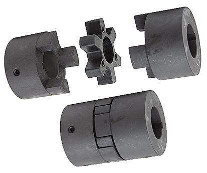
Framework: Adaptable pin tooth coupling
Adaptable or Rigid: Versatile
Regular or Nonstandard: Common
Substance: Steel
Merchandise title: LZD Versatile pin enamel coupling
Variety: LZD
Software: Industrial Products
Body Material: forty five# Steel
Color: Black
Dimension: Customized Size
Area Treatment: Blackening
MOQ: 1 Set
Certification: ISO9001:2015
Provider: 12 Months
Packaging Particulars: regular export packing and wood pallets packing
Port: ZheJiang port, Double elastomer versatile couplings TS38S-2 0571 045 Factory Price non-normal tailored 45# metal created in China China
Company Details
Our Solutions
Make contact with us
Certifications
Packaging & Delivery
Programs
FAQ
Programming With Couplings
A coupling is a mechanical device that connects two shafts together and transmits power. Its purpose is to join rotating equipment and allows some degree of end-movement or misalignment. There are many different types of couplings. It’s important to choose the right one for your application.
Mechanical connection between two shafts
There are many ways to achieve mechanical connection between two shafts, including the use of a coupling. One common type is the beam coupling, which is also known as a helical coupling. It is used for transmission of torque between two shafts. This type of connection accommodates axial, parallel and angular misalignments.
The hubs and shafts of a worm gear are connected together by a coupling. This mechanical connection allows one shaft to turn another without causing a mechanical failure. This type of coupling is made from sliding or rubbing parts to transfer torque. However, the coupling is not designed to withstand jerks, so it isn’t suitable for high-speed applications.
The use of a coupling is common in machinery and equipment. It helps transmit power from one drive shaft to the other, while adding mechanical flexibility. It is also useful for reducing the impact and vibration caused by misalignment. It also protects the drive shaft components from wear and tear.
A double-hook coupling can be used to provide a uniform angular velocity at the driven shaft. Another example is a double-jointed coupling. A double-jointed coupling can be used to connect shafts that are not directly intersecting. The double-jointed yoke can be used for the same purpose.
A shaft coupling is a device that maintains a strong mechanical connection between two shafts. It transfers motion from one shaft to another, at all loads and misalignments. Unlike a conventional linkage, a shaft coupling isn’t designed to allow relative motion between the two shafts. Couplings often serve several purposes in a machine, but their primary use is torque and power transmission.
Functions that control the flow of another function
One of the simplest programming constructs is a function that controls the flow of another function. A function can take an argument and return a different value, but it must be ready to return before it can pass that value to another function. To do this, you can use the goto statement and the if statement. Another way to control flow is to use a conditional statement.
Criteria for selecting a coupling
There are several important factors to consider when choosing the right coupling. One of the most important factors is coupling stiffness, which depends on the material used and the shape. The stiffness of a coupling determines its ability to resist elastic deformation. A stiff coupling is desirable for certain types of applications, but it’s undesirable for others. Stiffness can reduce the performance of a system if there’s too much inertia. To avoid this, ensure that the coupling you choose is within the recommended limits.
The size of a coupling is also important. Different coupling types can accommodate different shaft sizes and shapes. Some couplings have special features, such as braking and shear pin protection. When choosing a coupling, you should also consider the type of driven equipment. If you need to connect a high-torque motor, for example, you’ll want to choose a gear coupling. Likewise, a high-speed machine may require a disc coupling.
Another factor to consider when selecting a coupling is the torque rating. Despite its importance, it’s often underestimated. The torque rating is defined as the torque of the coupling divided by its OD. In some cases, torque may fluctuate during a cycle, requiring a coupling with a higher torque rating.
Torsionally flexible couplings are also important to consider. Their design should be able to withstand the torque required during operation, as well as the required speed. The coupling should also have a high degree of torsional stiffness, as well as damping. Furthermore, a damping coupling can reduce the energy wasted through vibration.
The sizing of a coupling is also determined by the torque. Many engineers use torque to select the correct coupling size, but they also take into consideration torsional flexibility and torsional stiffness. For example, a shaft may be able to handle large torque without damaging the coupling, while a disk may be unable to handle large amounts of torque.
Besides torque, another important consideration in coupling selection is the cost. While a coupling may be cheaper, it may be less reliable or easier to maintain. Couplings that are difficult to service may not last as long. They may also require frequent maintenance. If that’s the case, consider purchasing a coupling with a low service factor.
There are many different types of couplings. Some require additional lubrication throughout their lifetime, while others are 100% lubrication-free. An example of a 100% lubrication-free coupling is the RBI flexible coupling from CZPT. This type of coupling can significantly reduce your total cost of ownership.
In addition to the above-mentioned benefits, elastomeric couplings are low-cost and need little maintenance. While they are often cheaper than metallic couplings, they also have excellent shock absorption and vibration dampening properties. However, they are susceptible to high temperatures. Also, they are difficult to balance as an assembly, and have limited overload torque capacity.
editor by czh 2023-03-19
China High quality LZ cross slide coupling sliding/quick release coupling D16L30 high torque servo motor stepping screw coupler dry break coupling
Relevant Industries: Resorts, Garment Shops, Building Materials Shops, Production Plant, Machinery Repair Outlets, Food & Beverage Manufacturing facility, Farms, Cafe, Property Use, Retail, Meals Store, Printing Outlets, Construction works , Strength & Mining, Foods & Beverage Outlets, Advertising Firm, Other
Tailored help: OEM
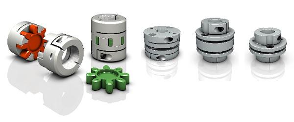
Structure: Jaw / Spider
Flexible or Rigid: Flexible
Normal or Nonstandard: Normal
Substance: Aluminium
Type: Substantial Transmission Performance Coupling
Software: Shaft Connections
Physique Materials: Aluminum Alloy
Title: Electrical power Transimisson Coupling
Search term: Elastic Coupling Areas
Attributes 1: Substantial Torque Large Rigidity
Attribute: Prolonged Operating Life
Approach: Cnc Turning
Packing: Carton
Merchandise identify: Tyre Coupling
Specification
| item | value |
| Applicable Industries | Manufacturing Plant, Restaurant, Printing Retailers |
| Customized help | OEM |
| Flexible or Rigid | Flexible |
| Standard or Nonstandard | Standard |
| Material | Aluminium |
| Brand Identify | HLTNC |
| Place of Origin | China |
| Product title | Flexible Couplings Coupler |
| Type | Flexible Clamp Coupling |
| Application | Shaft Connections |
| Body Materials | Aluminum Alloy |
| Name | Power Transimisson Coupling |
| Keyword | Elastic Coupling Components |
| Features 1 | High Torque Higher Rigidity |
| Feature | Long Operating Existence |
| Packing | Carton |
| Process | Cnc Turning |
What Is a Coupling?
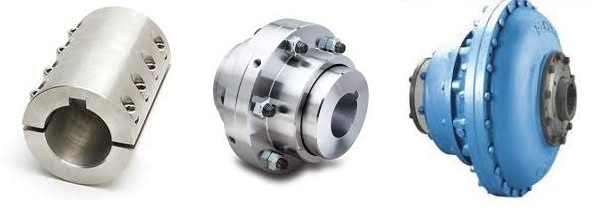
A coupling is a device used to connect two shafts. It transmits power between them and allows for some misalignment or end movement. There are several types of couplings. The most common ones are gear couplings and planetary couplings. However, there are many others as well.
Transfer of energy
Energy coupling is a process by which two biological reactions are linked by sharing energy. The energy released during one reaction can be used to drive the second. It is a very useful mechanism that synchronizes two biological systems. All cells have two types of reactions, exergonic and endergonic, and they are connected through energy coupling.
This process is important for a number of reasons. The first is that it allows the exchange of electrons and their energy. In a single molecule, this energy transfer involves the exchange of two electrons of different energy and spin. This exchange occurs because of the overlap interaction of two MOs.
Secondly, it is possible to achieve quadratic coupling. This is a phenomenon that occurs in circular membrane resonators when the system is statically deflected. This phenomenon has been gaining a great deal of interest as a mechanism for stronger coupling. If this mechanism is employed in a physical system, energy can be transferred on a nanometer scale.
The magnetic field is another important factor that affects the exchange of energy between semiconductor QWs. A strong magnetic field controls the strength of the coupling and the energy order of the exciton. The magnetic field can also influence the direction of polariton-mediated energy transfer. This mechanism is very promising for controlling the routing of excitation in a semiconductor.
Functions
Couplings play a variety of functions, including transferring power, compensating for misalignment, and absorbing shock. These functions depend on the type of shaft being coupled. There are four basic types: angular, parallel, and symmetrical. In many cases, coupling is necessary to accommodate misalignment.
Couplings are mechanical devices that join two rotating pieces of equipment. They are used to transfer power and allow for a small degree of end-to-end misalignment. This allows them to be used in many different applications, such as the transmission from the gearbox to the differential in an automobile. In addition, couplings can be used to transfer power to spindles.
Types
There are two main types of couplings: rigid and flexible. Rigid couplings are designed to prevent relative motion between the two shafts and are suitable for applications where precise alignment is required. However, high stresses in the case of significant misalignment can cause early failure of the coupling. Flexible couplings, on the other hand, allow for misalignment and allow for torque transmission.
A software application may exhibit different types of coupling. The first type involves the use of data. This means that one module may use data from another module for its operation. A good example of data coupling is the inheritance of an object. In a software application, one module can use another module’s data and parameters.
Another type of coupling is a rigid sleeve coupling. This type of coupling has a pipe with a bore that is finished to a specified tolerance. The pipe contains two threaded holes for transmitting torque. The sleeve is secured by a gib head key. This type of coupling may be used in applications where a couple of shafts are close together.
Other types of coupling include common and external. Common coupling occurs when two modules share global data and communication protocols. This type of coupling can lead to uncontrollable error propagation and unforeseen side effects when changes are made to the system. External coupling, on the other hand, involves two modules sharing an external device interface or communication protocol. Both types of coupling involve a shared code structure and depend on the external modules or hardware.
Mechanical couplings are essential in power transmission. They connect rotating shafts and can either be rigid or flexible, depending on the accuracy required. These couplings are used in pumps, compressors, motors, and generators to transmit power and torque. In addition to transferring power, couplings can also prevent torque overload.
Applications
Different coupling styles are ideal for different applications, and they have different characteristics that influence the coupling’s reliability during operation. These characteristics include stiffness, misalignment capability, ease of installation and maintenance, inherent balance, and speed capability. Selecting the right coupling style for a particular application is essential to minimize performance problems and maximize utility.
It is important to know the requirements for the coupling you choose before you start shopping. A proper selection process takes into account several design criteria, including torque and rpm, acoustic signals, and environmental factors. Once you’ve identified these parameters, you can select the best coupling for the job.
A gear coupling provides a mechanical connection between two rotating shafts. These couplings use gear mesh to transmit torque and power between two shafts. They’re typically used on large industrial machines, but they can also be used in smaller motion control systems. In smaller systems, a zero-backlash coupling design is ideal.
Another type of coupling is the flange coupling. These are easy to manufacture. Their design is similar to a sleeve coupling. But unlike a sleeve coupling, a flange coupling features a keyway on one side and two threaded holes on the other. These couplings are used in medium-duty industrial applications.
Besides being useful for power transmission, couplings can also prevent machine vibration. If vibration occurs in a machine, it can cause it to deviate from its predetermined position, or damage the motor. Couplings, however, help prevent this by absorbing the vibration and shock and preventing damage to expensive parts.
Couplings are heavily used in the industrial machinery and electrical industries. They provide the necessary rotation mechanism required by machinery and other equipment. Coupling suppliers can help customers find the right coupling for a specific application.
Criteria for selecting a coupling
When selecting a coupling for a specific application, there are a number of different factors to consider. These factors vary greatly, as do operating conditions, so selecting the best coupling for your system can be challenging. Some of these factors include horsepower, torque, and speed. You also need to consider the size of the shafts and the geometry of the equipment. Space restrictions and maintenance and installation requirements should also be taken into account. Other considerations can be specific to your system, such as the need for reversing.
First, determine what size coupling you need. The coupling’s size should be able to handle the torque required by the application. In addition, determine the interface connection, such as straight or tapered keyed shafts. Some couplings also feature integral flange connections.
During the specification process, be sure to specify which materials the coupling will be made of. This is important because the material will dictate most of its performance characteristics. Most couplings are made of stainless steel or aluminum, but you can also find ones made of Delrin, titanium, or other engineering-grade materials.
One of the most important factors to consider when selecting a coupling is its torque capability. If the torque rating is not adequate, the coupling can be damaged or break easily. Torque is a major factor in coupling selection, but it is often underestimated. In order to ensure maximum coupling performance, you should also take into consideration the size of the shafts and hubs.
In some cases, a coupling will need lubrication throughout its lifecycle. It may need to be lubricated every six months or even once a year. But there are couplings available that require no lubrication at all. An RBI flexible coupling by CZPT is one such example. Using a coupling of this kind can immediately cut down your total cost of ownership.
editor by czh