Product Description
Flexible Spring Coupling GD Electrical High Torque Connection Elastic Coupling For Encoder Step Motor
Description of Flexible Spring Coupling GD Electrical High Torque Connection Elastic Coupling For Encoder Step Motor
>The main body is made of zinc alloy
>The middle elastomer is made of spring steel
>It has the advantages of simple structure, good flexibility, low inertia and less allowable angular deviation
>Easy installation, spring steel more effective compensation radial, shaft deviation
>Suitable for micro motor and encoder
>Fastening method of set screw
Catalogue of Flexible Spring Coupling GD Electrical High Torque Connection Elastic Coupling For Encoder Step Motor
|
model parameter |
common bore diameter d1,d2 |
ΦD |
L |
LF |
F |
M |
tightening screw torque |
|
GD-16 x27 |
5,6,6.35,7,8,9,10 |
16 |
27 |
8.5 |
3 |
M3 |
0.7 |
|
GD-16 x35 |
5,6,6.35,7,8,9,10 |
16 |
35 |
12.5 |
3.5 |
M4 |
1.7 |
|
GD-26 x50 |
6,6.35,7,8,9,10,11,12,12.7,14 |
26 |
50 |
17 |
4.5 |
M5 |
4 |
|
model parameter |
Rated torque(N.m) |
Maximum torque(N.M) |
maximum speed (rpm) |
moment of inertia(Kg.M2) |
allowable eccentricity(mm) |
allowable deflection angle(°) |
weight (g) |
|
GD-16 x27 |
0.5 |
1 |
3000 |
1.02×10⁻⁶ |
1 |
8 |
30 |
|
GD-16 x35 |
0.5 |
1 |
3000 |
1.02×10⁻⁶ |
1 |
8 |
70 |
|
GD-26 x50 |
1.5 |
3 |
3000 |
1.15×10⁻⁵ |
1.2 |
8 |
130 |
/* January 22, 2571 19:08:37 */!function(){function s(e,r){var a,o={};try{e&&e.split(“,”).forEach(function(e,t){e&&(a=e.match(/(.*?):(.*)$/))&&1
High-Speed Rotations and Signal Accuracy in Encoder Couplings
Encoder couplings are designed to handle high-speed rotations while maintaining accurate signal transmission between the encoder and the driven shaft. Several factors contribute to their ability to achieve this:
1. Precision Manufacturing: Encoder couplings are manufactured with high precision to ensure minimal runout and concentricity errors. This precision minimizes vibrations and ensures accurate signal transmission at high speeds.
2. Low Backlash: Many encoder couplings are designed to have minimal or zero backlash. Backlash refers to the play or movement between the coupling’s mating components. Low backlash reduces signal inaccuracies caused by sudden changes in direction or speed.
3. Balanced Design: Balanced design helps distribute forces and torques evenly across the coupling, reducing the likelihood of vibration-induced signal distortions during high-speed rotations.
4. Material Selection: The choice of materials with suitable mechanical properties plays a role in achieving high-speed performance. Materials with low density and high strength help minimize the coupling’s mass while maintaining structural integrity.
5. Vibration Damping: Some encoder couplings incorporate vibration-damping features, such as elastomeric inserts, to mitigate vibrations and oscillations generated during high-speed rotations.
6. Dynamic Balance: Encoder couplings may undergo dynamic balancing to ensure that any uneven mass distribution is corrected, further reducing vibrations at high speeds.
7. Bearing Support: Proper bearing support on both sides of the encoder coupling helps maintain alignment and reduces stress on the coupling and encoder shaft, enhancing signal accuracy.
Encoder couplings are engineered to offer high-speed capabilities while preserving signal accuracy, making them suitable for applications where precision motion control and signal integrity are critical.
Best Practices for Minimizing Electrical Interference in Encoder Coupling Systems
Electrical interference can adversely affect the performance and accuracy of encoder coupling systems. To minimize such interference and ensure reliable signal transmission, consider the following best practices:
- Proper Grounding: Ensure that all components in the system are properly grounded to a common ground point. Grounding helps mitigate the buildup of static charges and reduces the risk of electrical noise affecting the encoder signal.
- Shielding: Use shielded cables for connecting the encoder to the controller. Shielding helps prevent external electromagnetic interference from reaching the signal wires and affecting the encoder output.
- Separation from Power Lines: Keep encoder cables and signal wires physically separated from high-voltage power lines, motors, and other sources of electromagnetic interference. This reduces the likelihood of induced noise affecting the encoder signal.
- Ferrite Beads: Employ ferrite beads or chokes on the signal cables near the encoder connection points. Ferrite beads suppress high-frequency noise and can be effective in minimizing electrical interference.
- Ground Loops: Avoid ground loops, which occur when there are multiple paths for current to flow between different ground points. Ground loops can introduce unwanted noise. Use single-point grounding and minimize ground loop formation.
- Isolation: Employ isolation techniques, such as optical isolation or transformer-based signal conditioning, to electrically isolate the encoder from the rest of the system. This prevents the propagation of noise between components.
- EMI Filters: Install electromagnetic interference (EMI) filters on the power supply lines to reduce conducted interference from reaching the encoder. These filters can help maintain clean power and reduce noise.
- Proper Cable Routing: Ensure that encoder cables are routed away from sources of interference and are kept as short as possible. Avoid sharp bends and kinks in the cables, which can lead to signal degradation.
- Grounding Practices: Follow proper grounding practices, such as using star grounding and minimizing ground connections. Avoid daisy-chaining ground connections, as this can increase the risk of interference.
Implementing these best practices will help minimize electrical interference and ensure that the encoder coupling system maintains accurate signal transmission, resulting in improved performance and reliability.
Facilitating Precise Signal Transmission with Encoder Couplings
An encoder coupling plays a crucial role in facilitating precise signal transmission between the encoder and the shaft in motion control and automation systems. Here’s how it works:
1. Minimizing Misalignment: Encoder couplings are designed to accommodate various types of misalignment, including angular, axial, and radial misalignment. By allowing controlled flexibility, the coupling minimizes the stress on both the encoder and the shaft, ensuring accurate signal transmission.
2. Reducing Backlash: Backlash is the amount of movement a system can experience before the motion is effectively transferred. High-quality encoder couplings have minimal backlash, ensuring that the encoder’s output accurately corresponds to the shaft’s movement.
3. Increasing Torque Transmission: Encoder couplings provide efficient torque transmission between the encoder and the shaft, allowing the encoder to accurately detect changes in position or speed.
4. Enhancing Response Time: The mechanical properties of the encoder coupling ensure that any changes in the shaft’s position or movement are promptly transmitted to the encoder. This results in a faster response time and more accurate signal feedback.
5. Reducing Signal Disturbances: Vibrations, shocks, and other disturbances in machinery can negatively impact signal accuracy. A well-designed encoder coupling dampens vibrations and disturbances, ensuring that the encoder receives a clean and accurate signal.
6. Compensating for Thermal Expansion: In some applications, temperature changes can cause the shaft and encoder to expand or contract at different rates. Encoder couplings accommodate these thermal variations, preventing signal discrepancies caused by thermal expansion.
Overall, the encoder coupling acts as a reliable intermediary between the encoder and the shaft, ensuring that the signal accurately reflects the shaft’s position, speed, and movement. This precise signal transmission is essential for the accurate control and performance of motion control and automation systems.


editor by CX 2024-04-30
China Good quality Flexible Spring Coupling Gd Electrical High Torque Connection Elastic Coupling for Encoder Step Motor
Product Description
Flexible Spring Coupling GD Electrical High Torque Connection Elastic Coupling For Encoder Step Motor
Description of Flexible Spring Coupling GD Electrical High Torque Connection Elastic Coupling For Encoder Step Motor
>The main body is made of zinc alloy
>The middle elastomer is made of spring steel
>It has the advantages of simple structure, good flexibility, low inertia and less allowable angular deviation
>Easy installation, spring steel more effective compensation radial, shaft deviation
>Suitable for micro motor and encoder
>Fastening method of set screw
Catalogue of Flexible Spring Coupling GD Electrical High Torque Connection Elastic Coupling For Encoder Step Motor
|
model parameter |
common bore diameter d1,d2 |
ΦD |
L |
LF |
F |
M |
tightening screw torque |
|
GD-16 x27 |
5,6,6.35,7,8,9,10 |
16 |
27 |
8.5 |
3 |
M3 |
0.7 |
|
GD-16 x35 |
5,6,6.35,7,8,9,10 |
16 |
35 |
12.5 |
3.5 |
M4 |
1.7 |
|
GD-26 x50 |
6,6.35,7,8,9,10,11,12,12.7,14 |
26 |
50 |
17 |
4.5 |
M5 |
4 |
|
model parameter |
Rated torque(N.m) |
Maximum torque(N.M) |
maximum speed (rpm) |
moment of inertia(Kg.M2) |
allowable eccentricity(mm) |
allowable deflection angle(°) |
weight (g) |
|
GD-16 x27 |
0.5 |
1 |
3000 |
1.02×10⁻⁶ |
1 |
8 |
30 |
|
GD-16 x35 |
0.5 |
1 |
3000 |
1.02×10⁻⁶ |
1 |
8 |
70 |
|
GD-26 x50 |
1.5 |
3 |
3000 |
1.15×10⁻⁵ |
1.2 |
8 |
130 |
/* January 22, 2571 19:08:37 */!function(){function s(e,r){var a,o={};try{e&&e.split(“,”).forEach(function(e,t){e&&(a=e.match(/(.*?):(.*)$/))&&1
Diagnosing Potential Issues in Encoder Couplings
Identifying potential issues in encoder couplings is crucial for maintaining optimal performance. Some signs to watch for and diagnostic steps include:
1. Signal Inaccuracies: Inaccurate position or velocity feedback signals may indicate coupling misalignment. Use diagnostic tools to compare expected and actual readings.
2. Increased Noise: Unusual vibrations or noise during operation can indicate misalignment or wear. Perform vibration analysis or inspect the coupling for visual damage.
3. Signal Dropouts: Intermittent signal loss or dropouts can be due to poor coupling engagement or damaged wiring. Check wiring connections and the coupling’s mechanical integrity.
4. Drifting Position: If the controlled system’s position drifts over time, it could suggest issues in the encoder coupling’s precision. Monitor position deviations and inspect the coupling for wear.
5. Excessive Heating: Overheating of the coupling may point to misalignment or excessive friction. Monitor the temperature and ensure proper coupling lubrication.
6. Irregular Movement: Unexpected jerks or irregular motion can indicate binding or sticking in the coupling. Inspect the coupling’s components for damage or obstruction.
7. Reduced Accuracy: Decreased accuracy in positioning or velocity control might be due to backlash or wear. Measure and compare desired and achieved positions for accuracy assessment.
8. Excessive Wear: Visual inspection of the coupling’s components for signs of wear, such as cracked or deformed elements, can help detect potential issues early.
9. Misalignment: Misalignment between the encoder and the shaft can lead to signal discrepancies. Use precision measurement tools to assess alignment and adjust if necessary.
10. Visual Inspection: Regularly inspect the coupling for signs of corrosion, rust, or physical damage. Address any issues promptly to prevent further deterioration.
Performing routine maintenance, using diagnostic tools, and monitoring the system’s performance can help identify and address potential issues in encoder couplings, ensuring consistent and accurate motion control.
Proper Installation and Maintenance of Encoder Couplings
Proper installation and maintenance are essential for ensuring the optimal performance and longevity of encoder couplings. Here’s a step-by-step guide:
1. Installation:
- Ensure Proper Alignment: Align the encoder coupling and shafts precisely to minimize misalignment, which can lead to signal loss and premature wear.
- Secure Fasteners: Tighten fasteners according to manufacturer specifications to prevent coupling slippage and maintain signal accuracy.
- Check Clearances: Ensure there’s enough clearance between the encoder coupling and surrounding components to prevent interference during operation.
- Use Proper Tools: Use appropriate tools and techniques during installation to avoid damaging the encoder coupling or other components.
2. Initial Testing:
- Perform System Check: After installation, conduct initial tests to verify proper signal transmission and alignment. Address any issues promptly.
- Check Signal Integrity: Use appropriate testing equipment to verify that the encoder signals are accurate and consistent.
3. Regular Maintenance:
- Visual Inspection: Regularly inspect the encoder coupling for signs of wear, damage, or misalignment. Look for cracks, corrosion, or other irregularities.
- Lubrication: If the encoder coupling requires lubrication, follow manufacturer guidelines to ensure proper lubricant application and prevent excessive wear.
- Cleanliness: Keep the encoder coupling and its surroundings clean to prevent debris and contaminants from affecting performance.
- Monitor Temperature: Monitor operating temperatures to ensure the encoder coupling remains within its recommended temperature range.
4. Preventive Measures:
- Regular Checkups: Schedule periodic maintenance and inspections to catch potential issues before they lead to significant problems.
- Alignment Checks: Regularly verify shaft alignment to maintain accurate signal transmission and prevent premature wear.
- Replace as Needed: If the encoder coupling shows signs of significant wear, damage, or signal degradation, consider replacing it to avoid system failures.
5. Follow Manufacturer Recommendations:
- Adhere to the manufacturer’s installation, maintenance, and lubrication guidelines to ensure optimal performance and maintain warranty coverage.
By following these installation and maintenance practices, you can ensure that your encoder coupling functions reliably and efficiently, contributing to the overall performance of your motion control or automation system.
Challenges of Misalignment and How Encoder Couplings Address Them
Misalignment in mechanical systems occurs when the rotational axes of connected components are not perfectly aligned. This misalignment can lead to various issues, including reduced efficiency, increased wear, and even component failure. Encoder couplings play a crucial role in mitigating the challenges posed by misalignment. Here’s how they address these challenges:
1. Angular Misalignment: Encoder couplings can accommodate a certain degree of angular misalignment between the encoder and the driven component. They use flexible elements, such as elastomers or metal bellows, to allow for slight angular deviations without transmitting excessive stress to the connected components.
2. Radial Misalignment: Radial misalignment occurs when the axes of the encoder and the driven component are offset. Encoder couplings with flexible elements can absorb the radial displacement, preventing undue stress on the shafts and bearings. This helps extend the lifespan of the components and reduces the risk of premature failure.
3. Axial Misalignment: Axial misalignment refers to the axial offset between the encoder and the driven component. Encoder couplings with axial flexibility, such as certain types of beam or bellows couplings, can accommodate axial movement while maintaining effective signal transmission. This is particularly important in systems where thermal expansion or contraction may occur.
4. Vibration Damping: Misalignment can lead to vibrations that propagate through the system, affecting overall performance and accuracy. Encoder couplings with vibration-damping features help minimize the impact of these vibrations, ensuring smoother and more precise motion control.
5. Reduced Wear and Stress: Misalignment can increase wear and stress on shafts, bearings, and other components. Encoder couplings that effectively address misalignment help distribute loads more evenly, reducing wear and the likelihood of premature component failure.
6. Preserving Encoder Integrity: In systems with encoders, misalignment can compromise the accuracy of signal transmission, leading to measurement inaccuracies. Encoder couplings maintain the alignment necessary for accurate signal transmission, preserving the integrity of the encoder’s output.
Overall, encoder couplings provide the flexibility and compensation needed to accommodate misalignment while ensuring efficient and accurate signal transmission. By addressing misalignment challenges, these couplings contribute to the reliability, performance, and longevity of motion control and automation systems.
editor by CX 2024-04-19
China Best Sales Glt-68X74 Glt Double Diaphragm Flexible Shaft Coupling for Shaft Encoder Step Motor
Product Description
GLT-68×74 GLT Double Diaphragm Flexible Shaft Coupling For Shaft Encoder Step Motor
Description of GLT-68×74 GLT Double Diaphragm Flexible Shaft Coupling For Shaft Encoder Step Motor
>High torque rigidity, can accurately control the rotation of the shaft, can carry out high-precision control
>Designed for servo and stepping motor
>No gap between the shaft and sleeve connection, general for positive and negative rotation
>Low inertia, suitable for high speed operation
>The diaphragm is made of spring steel with excellent fatigue resistance
Catalogue of GLT-68×74 GLT Double Diaphragm Flexible Shaft Coupling For Shaft Encoder Step Motor
|
model parameter |
common bore diameter d1,d2 |
ΦD |
ΦN |
L |
LF |
d3 |
LP |
S |
tightening screw torque |
|
GLT-34×37.5 |
5,6,6.35,7,8,9,9.525,10,11,12, |
34 |
21.6 |
37.5 |
12.15 |
Φ16 |
6.8 |
3.2 |
1.5 |
|
GLT-39×48 |
6,8,9,9.525,10,11,12,12.7,14,15 |
39 |
25 |
48 |
15.15 |
Φ19 |
9.3 |
4.5 |
2.5 |
|
GLT-44×48 |
6,8,9,9.525,10,11,12,12.7,14,15,16,17,18 |
44 |
29.6 |
48 |
15.15 |
Φ22.5 |
9.3 |
4.2 |
2.5 |
|
GLT-56×61 |
10,12,12.7,14,15,16,17,18,19,20,22,24 |
56 |
38 |
61 |
19.9 |
Φ32.5 |
10.8 |
5.2 |
7 |
|
GLT-68×74 |
14,15,16,17,18,19,20,22,24,25,28,30 |
68 |
46 |
74 |
24 |
Φ38.3 |
14 |
6 |
12 |
|
GLT-82×98 |
17,18,19,20,22,24,25,28,30,32,35,38 |
82 |
56 |
98 |
30.15 |
Φ45 |
22.3 |
7.7 |
20 |
|
model parameter |
Rated torque(N.m) |
allowable eccentricity (mm) |
allowable deflection angle (°) |
allowable axial deviation (mm) |
maximum speed (rpm) |
static torsional stiffness (N.M/rad) |
weight (g) |
|
GLT-34×37.5 |
2 |
0.12 |
1.5 |
±0.18 |
10000 |
2200 |
49 |
|
GLT-39×48 |
4.5 |
0.15 |
1.5 |
±0.23 |
10000 |
4500 |
85 |
|
GLT-44×48 |
6.75 |
0.17 |
1.5 |
±0.27 |
10000 |
5500 |
107 |
|
GLT-56×61 |
20 |
0.17 |
1.5 |
±0.36 |
10000 |
11000 |
196 |
|
GLT-68×74 |
50 |
0.18 |
1.5 |
±0.4 |
9000 |
23000 |
375 |
|
GLT-82×98 |
90 |
0.18 |
1.5 |
±0.5 |
8000 |
38000 |
645 |
/* January 22, 2571 19:08:37 */!function(){function s(e,r){var a,o={};try{e&&e.split(“,”).forEach(function(e,t){e&&(a=e.match(/(.*?):(.*)$/))&&1
Comparison of Encoder Couplings with Other Coupling Types
When comparing encoder couplings with other coupling types, such as flexible couplings and magnetic couplings, several key factors come into play:
1. Flexibility: Encoder couplings, like flexible couplings, offer flexibility to accommodate misalignment between the encoder and the driven component. They provide angular, radial, and axial flexibility, ensuring efficient signal transmission while minimizing stress on components.
2. Signal Transmission: Encoder couplings are specifically designed to ensure accurate signal transmission between the encoder and the controlled system. This distinguishes them from other couplings that prioritize torque transmission, such as magnetic couplings used for sealing applications.
3. Backlash Reduction: Encoder couplings often prioritize low backlash to enhance the precision and accuracy of motion control systems. While some other coupling types also aim to minimize backlash, encoder couplings excel in this aspect due to their primary function of accurate signal transmission.
4. Magnetic Couplings: Magnetic couplings are commonly used for torque transmission across a sealed barrier, such as in pump applications. While they offer the advantage of hermetic sealing, they may not be as suitable for precise signal transmission as encoder couplings. Magnetic couplings can also introduce a certain amount of backlash due to their design.
5. Torque Capacity: Flexible couplings and some other types of couplings are often selected based on their torque capacity to transmit power between shafts. Encoder couplings, on the other hand, prioritize signal integrity and precision, making them ideal for applications where accurate motion control is essential.
6. Application Focus: Encoder couplings are specialized for motion control and automation systems that require precise positioning and accurate signal feedback. Other coupling types may have broader applications, including torque transmission, vibration dampening, and sealing.
7. Maintenance: Encoder couplings, like flexible couplings, require periodic inspection and maintenance to ensure proper functioning and accuracy. Magnetic couplings may have different maintenance requirements due to their sealing properties.
Overall, encoder couplings stand out in their ability to facilitate accurate signal transmission and precise motion control. While other coupling types have their own advantages and applications, encoder couplings are specifically tailored to meet the demands of motion control and automation systems where maintaining signal accuracy is paramount.
Impact of Encoder Resolution on Choice of Coupling
The encoder resolution plays a crucial role in selecting an appropriate coupling for your system. Encoder resolution refers to the number of distinct positions a rotary encoder can detect in one full rotation. Here’s how encoder resolution impacts the choice of coupling:
1. Precision Requirements:
Higher encoder resolutions provide finer position accuracy. If your application demands high precision and accuracy, such as in robotics or CNC machines, a coupling that minimizes backlash and offers precise torque transmission is essential.
2. Backlash Sensitivity:
As encoder resolution increases, the system becomes more sensitive to backlash (play between coupling components). To mitigate this, a coupling with minimal backlash, such as a zero-backlash or low-backlash coupling, is recommended to ensure accurate position feedback.
3. Dynamic Response:
Higher encoder resolutions allow systems to detect even small movements, improving dynamic response. For applications requiring rapid and accurate positioning changes, a coupling that provides high torsional stiffness and low wind-up is beneficial.
4. Mechanical Compliance:
Low-resolution encoders may tolerate some misalignment due to their coarser feedback intervals. However, high-resolution encoders are more sensitive to misalignment, making it important to choose a coupling that accommodates misalignment while maintaining signal accuracy.
5. Coupling Selection:
For high-resolution encoders, consider couplings that provide precision, low backlash, and accurate torque transmission, such as beam couplings, bellows couplings, or Oldham couplings. These couplings help maintain the integrity of position feedback and optimize system performance.
6. Environmental Factors:
The operating environment can affect the choice of coupling. For applications with extreme conditions, such as temperature fluctuations or aggressive chemicals, select a coupling material that can withstand these conditions without compromising the encoder’s accuracy.
Ultimately, the encoder resolution influences the coupling choice by demanding a coupling that complements the precision, accuracy, and dynamic performance required by the application.
Types of Encoder Couplings Tailored for Specific Applications
Encoder couplings come in various types, each tailored to suit specific applications and requirements:
1. Beam Couplings: These couplings use flexible beams to transmit motion and accommodate misalignments. They are ideal for applications requiring high precision and low backlash.
2. Bellows Couplings: Bellows couplings have accordion-like bellows that provide high torsional stiffness while allowing axial and angular misalignment compensation. They are commonly used in vacuum environments.
3. Oldham Couplings: Oldham couplings use a three-piece design to transmit motion. They provide high misalignment capacity while maintaining accurate motion transmission.
4. Disc Couplings: Disc couplings consist of thin metal discs that provide torsional stiffness and minimal backlash. They are suitable for high-speed and high-torque applications.
5. Flexible Shaft Couplings: These couplings use a flexible element, such as elastomer or rubber, to accommodate misalignments and dampen vibrations. They are versatile and used in various industries.
6. Miniature Couplings: Designed for small-scale applications, miniature couplings provide precise motion control in compact spaces, such as robotics and medical devices.
7. High-Torque Couplings: These couplings are built to handle high torque loads, making them suitable for heavy-duty industrial applications.
8. Magnetic Couplings: Magnetic couplings use magnets to transmit motion without physical contact. They are used in applications requiring hermetic sealing or where avoiding direct contact is necessary.
9. Encoder-Integrated Couplings: Some couplings come with built-in encoders for direct position sensing. These are convenient for applications where space is limited or where separate encoders are not practical.
10. Shaft Locking Mechanisms: Some couplings feature mechanisms that lock the shafts in place, providing additional security against shaft slippage.
The choice of encoder coupling type depends on factors like the level of misalignment, torque requirements, speed, space limitations, and specific application needs.
editor by CX 2024-04-12
China Standard Glt-44X48 Glt Double Diaphragm Flexible Clamp Coupling for Shaft Encoder Step Motor
Product Description
GLT-44×48 GLT Double Diaphragm Flexible Clamp Coupling For Shaft Encoder Step Motor
Description of GLT-44×48 GLT Double Diaphragm Flexible Clamp Coupling For Shaft Encoder Step Motor
>High torque rigidity, can accurately control the rotation of the shaft, can carry out high-precision control
>Designed for servo and stepping motor
>No gap between the shaft and sleeve connection, general for positive and negative rotation
>Low inertia, suitable for high speed operation
>The diaphragm is made of spring steel with excellent fatigue resistance
Catalogue of GLT-44×48 GLT Double Diaphragm Flexible Clamp Coupling For Shaft Encoder Step Motor
|
model parameter |
common bore diameter d1,d2 |
ΦD |
ΦN |
L |
LF |
d3 |
LP |
S |
tightening screw torque |
|
GLT-34×37.5 |
5,6,6.35,7,8,9,9.525,10,11,12, |
34 |
21.6 |
37.5 |
12.15 |
Φ16 |
6.8 |
3.2 |
1.5 |
|
GLT-39×48 |
6,8,9,9.525,10,11,12,12.7,14,15 |
39 |
25 |
48 |
15.15 |
Φ19 |
9.3 |
4.5 |
2.5 |
|
GLT-44×48 |
6,8,9,9.525,10,11,12,12.7,14,15,16,17,18 |
44 |
29.6 |
48 |
15.15 |
Φ22.5 |
9.3 |
4.2 |
2.5 |
|
GLT-56×61 |
10,12,12.7,14,15,16,17,18,19,20,22,24 |
56 |
38 |
61 |
19.9 |
Φ32.5 |
10.8 |
5.2 |
7 |
|
GLT-68×74 |
14,15,16,17,18,19,20,22,24,25,28,30 |
68 |
46 |
74 |
24 |
Φ38.3 |
14 |
6 |
12 |
|
GLT-82×98 |
17,18,19,20,22,24,25,28,30,32,35,38 |
82 |
56 |
98 |
30.15 |
Φ45 |
22.3 |
7.7 |
20 |
|
model parameter |
Rated torque(N.m) |
allowable eccentricity (mm) |
allowable deflection angle (°) |
allowable axial deviation (mm) |
maximum speed (rpm) |
static torsional stiffness (N.M/rad) |
weight (g) |
|
GLT-34×37.5 |
2 |
0.12 |
1.5 |
±0.18 |
10000 |
2200 |
49 |
|
GLT-39×48 |
4.5 |
0.15 |
1.5 |
±0.23 |
10000 |
4500 |
85 |
|
GLT-44×48 |
6.75 |
0.17 |
1.5 |
±0.27 |
10000 |
5500 |
107 |
|
GLT-56×61 |
20 |
0.17 |
1.5 |
±0.36 |
10000 |
11000 |
196 |
|
GLT-68×74 |
50 |
0.18 |
1.5 |
±0.4 |
9000 |
23000 |
375 |
|
GLT-82×98 |
90 |
0.18 |
1.5 |
±0.5 |
8000 |
38000 |
645 |
/* March 10, 2571 17:59:20 */!function(){function s(e,r){var a,o={};try{e&&e.split(“,”).forEach(function(e,t){e&&(a=e.match(/(.*?):(.*)$/))&&1
Comparison of Encoder Couplings with Other Coupling Types
When comparing encoder couplings with other coupling types, such as flexible couplings and magnetic couplings, several key factors come into play:
1. Flexibility: Encoder couplings, like flexible couplings, offer flexibility to accommodate misalignment between the encoder and the driven component. They provide angular, radial, and axial flexibility, ensuring efficient signal transmission while minimizing stress on components.
2. Signal Transmission: Encoder couplings are specifically designed to ensure accurate signal transmission between the encoder and the controlled system. This distinguishes them from other couplings that prioritize torque transmission, such as magnetic couplings used for sealing applications.
3. Backlash Reduction: Encoder couplings often prioritize low backlash to enhance the precision and accuracy of motion control systems. While some other coupling types also aim to minimize backlash, encoder couplings excel in this aspect due to their primary function of accurate signal transmission.
4. Magnetic Couplings: Magnetic couplings are commonly used for torque transmission across a sealed barrier, such as in pump applications. While they offer the advantage of hermetic sealing, they may not be as suitable for precise signal transmission as encoder couplings. Magnetic couplings can also introduce a certain amount of backlash due to their design.
5. Torque Capacity: Flexible couplings and some other types of couplings are often selected based on their torque capacity to transmit power between shafts. Encoder couplings, on the other hand, prioritize signal integrity and precision, making them ideal for applications where accurate motion control is essential.
6. Application Focus: Encoder couplings are specialized for motion control and automation systems that require precise positioning and accurate signal feedback. Other coupling types may have broader applications, including torque transmission, vibration dampening, and sealing.
7. Maintenance: Encoder couplings, like flexible couplings, require periodic inspection and maintenance to ensure proper functioning and accuracy. Magnetic couplings may have different maintenance requirements due to their sealing properties.
Overall, encoder couplings stand out in their ability to facilitate accurate signal transmission and precise motion control. While other coupling types have their own advantages and applications, encoder couplings are specifically tailored to meet the demands of motion control and automation systems where maintaining signal accuracy is paramount.
Impact of Encoder Resolution on Choice of Coupling
The encoder resolution plays a crucial role in selecting an appropriate coupling for your system. Encoder resolution refers to the number of distinct positions a rotary encoder can detect in one full rotation. Here’s how encoder resolution impacts the choice of coupling:
1. Precision Requirements:
Higher encoder resolutions provide finer position accuracy. If your application demands high precision and accuracy, such as in robotics or CNC machines, a coupling that minimizes backlash and offers precise torque transmission is essential.
2. Backlash Sensitivity:
As encoder resolution increases, the system becomes more sensitive to backlash (play between coupling components). To mitigate this, a coupling with minimal backlash, such as a zero-backlash or low-backlash coupling, is recommended to ensure accurate position feedback.
3. Dynamic Response:
Higher encoder resolutions allow systems to detect even small movements, improving dynamic response. For applications requiring rapid and accurate positioning changes, a coupling that provides high torsional stiffness and low wind-up is beneficial.
4. Mechanical Compliance:
Low-resolution encoders may tolerate some misalignment due to their coarser feedback intervals. However, high-resolution encoders are more sensitive to misalignment, making it important to choose a coupling that accommodates misalignment while maintaining signal accuracy.
5. Coupling Selection:
For high-resolution encoders, consider couplings that provide precision, low backlash, and accurate torque transmission, such as beam couplings, bellows couplings, or Oldham couplings. These couplings help maintain the integrity of position feedback and optimize system performance.
6. Environmental Factors:
The operating environment can affect the choice of coupling. For applications with extreme conditions, such as temperature fluctuations or aggressive chemicals, select a coupling material that can withstand these conditions without compromising the encoder’s accuracy.
Ultimately, the encoder resolution influences the coupling choice by demanding a coupling that complements the precision, accuracy, and dynamic performance required by the application.
Importance of Backlash Reduction in Encoder Couplings
Backlash reduction is a critical consideration when selecting encoder couplings, particularly in motion control and automation applications that require precision and accuracy. Backlash refers to the angular or linear movement that occurs when the direction of motion changes in a mechanical system.
In encoder couplings, backlash can lead to inaccuracies in signal transmission between the encoder and the driven component. This is especially problematic in applications that involve rapid changes in direction or require precise positioning. The importance of backlash reduction can be understood through the following points:
1. Precision: Backlash can introduce errors in the measurement or position control process. As the system changes direction, the backlash can cause a delay in the response of the encoder, leading to inaccurate position readings or control commands.
2. Repeatability: Systems that require consistent and repeatable motion rely on accurate signal transmission. Backlash can lead to inconsistencies in positioning, making it difficult to achieve the desired level of repeatability.
3. Minimized Error Accumulation: In applications that involve multiple movements and direction changes, backlash can accumulate and lead to a cumulative error over time. This can result in a significant deviation from the intended position or motion path.
4. Smooth Operation: Backlash can cause jerky or uneven motion transitions, affecting the overall smoothness of operation. In applications where smooth and continuous motion is crucial, backlash reduction becomes essential.
5. Feedback Loop Integrity: Many encoder systems rely on closed-loop feedback control to maintain accuracy. Backlash can disrupt the feedback loop, causing the system to overcompensate for the movement delay and leading to instability.
6. System Efficiency: Backlash can result in energy loss and mechanical stress as the system compensates for the delay in movement. This can reduce the overall efficiency of the system.
To address these challenges, encoder couplings are designed with features that minimize backlash. Coupling designs may incorporate mechanisms such as preloading, spring elements, or specialized materials that reduce the clearance between components, effectively reducing or eliminating backlash. By selecting encoder couplings with reduced backlash, motion control and automation systems can achieve higher levels of accuracy, repeatability, and overall performance.
editor by CX 2024-02-04
China best Glt-68X74 Glt Double Diaphragm Flexible Shaft Coupling for Shaft Encoder Step Motor
Product Description
GLT-68×74 GLT Double Diaphragm Flexible Shaft Coupling For Shaft Encoder Step Motor
Description of GLT-68×74 GLT Double Diaphragm Flexible Shaft Coupling For Shaft Encoder Step Motor
>High torque rigidity, can accurately control the rotation of the shaft, can carry out high-precision control
>Designed for servo and stepping motor
>No gap between the shaft and sleeve connection, general for positive and negative rotation
>Low inertia, suitable for high speed operation
>The diaphragm is made of spring steel with excellent fatigue resistance
Catalogue of GLT-68×74 GLT Double Diaphragm Flexible Shaft Coupling For Shaft Encoder Step Motor
|
model parameter |
common bore diameter d1,d2 |
ΦD |
ΦN |
L |
LF |
d3 |
LP |
S |
tightening screw torque |
|
GLT-34×37.5 |
5,6,6.35,7,8,9,9.525,10,11,12, |
34 |
21.6 |
37.5 |
12.15 |
Φ16 |
6.8 |
3.2 |
1.5 |
|
GLT-39×48 |
6,8,9,9.525,10,11,12,12.7,14,15 |
39 |
25 |
48 |
15.15 |
Φ19 |
9.3 |
4.5 |
2.5 |
|
GLT-44×48 |
6,8,9,9.525,10,11,12,12.7,14,15,16,17,18 |
44 |
29.6 |
48 |
15.15 |
Φ22.5 |
9.3 |
4.2 |
2.5 |
|
GLT-56×61 |
10,12,12.7,14,15,16,17,18,19,20,22,24 |
56 |
38 |
61 |
19.9 |
Φ32.5 |
10.8 |
5.2 |
7 |
|
GLT-68×74 |
14,15,16,17,18,19,20,22,24,25,28,30 |
68 |
46 |
74 |
24 |
Φ38.3 |
14 |
6 |
12 |
|
GLT-82×98 |
17,18,19,20,22,24,25,28,30,32,35,38 |
82 |
56 |
98 |
30.15 |
Φ45 |
22.3 |
7.7 |
20 |
|
model parameter |
Rated torque(N.m) |
allowable eccentricity (mm) |
allowable deflection angle (°) |
allowable axial deviation (mm) |
maximum speed (rpm) |
static torsional stiffness (N.M/rad) |
weight (g) |
|
GLT-34×37.5 |
2 |
0.12 |
1.5 |
±0.18 |
10000 |
2200 |
49 |
|
GLT-39×48 |
4.5 |
0.15 |
1.5 |
±0.23 |
10000 |
4500 |
85 |
|
GLT-44×48 |
6.75 |
0.17 |
1.5 |
±0.27 |
10000 |
5500 |
107 |
|
GLT-56×61 |
20 |
0.17 |
1.5 |
±0.36 |
10000 |
11000 |
196 |
|
GLT-68×74 |
50 |
0.18 |
1.5 |
±0.4 |
9000 |
23000 |
375 |
|
GLT-82×98 |
90 |
0.18 |
1.5 |
±0.5 |
8000 |
38000 |
645 |
/* March 10, 2571 17:59:20 */!function(){function s(e,r){var a,o={};try{e&&e.split(“,”).forEach(function(e,t){e&&(a=e.match(/(.*?):(.*)$/))&&1
Comparison of Encoder Couplings with Other Coupling Types
When comparing encoder couplings with other coupling types, such as flexible couplings and magnetic couplings, several key factors come into play:
1. Flexibility: Encoder couplings, like flexible couplings, offer flexibility to accommodate misalignment between the encoder and the driven component. They provide angular, radial, and axial flexibility, ensuring efficient signal transmission while minimizing stress on components.
2. Signal Transmission: Encoder couplings are specifically designed to ensure accurate signal transmission between the encoder and the controlled system. This distinguishes them from other couplings that prioritize torque transmission, such as magnetic couplings used for sealing applications.
3. Backlash Reduction: Encoder couplings often prioritize low backlash to enhance the precision and accuracy of motion control systems. While some other coupling types also aim to minimize backlash, encoder couplings excel in this aspect due to their primary function of accurate signal transmission.
4. Magnetic Couplings: Magnetic couplings are commonly used for torque transmission across a sealed barrier, such as in pump applications. While they offer the advantage of hermetic sealing, they may not be as suitable for precise signal transmission as encoder couplings. Magnetic couplings can also introduce a certain amount of backlash due to their design.
5. Torque Capacity: Flexible couplings and some other types of couplings are often selected based on their torque capacity to transmit power between shafts. Encoder couplings, on the other hand, prioritize signal integrity and precision, making them ideal for applications where accurate motion control is essential.
6. Application Focus: Encoder couplings are specialized for motion control and automation systems that require precise positioning and accurate signal feedback. Other coupling types may have broader applications, including torque transmission, vibration dampening, and sealing.
7. Maintenance: Encoder couplings, like flexible couplings, require periodic inspection and maintenance to ensure proper functioning and accuracy. Magnetic couplings may have different maintenance requirements due to their sealing properties.
Overall, encoder couplings stand out in their ability to facilitate accurate signal transmission and precise motion control. While other coupling types have their own advantages and applications, encoder couplings are specifically tailored to meet the demands of motion control and automation systems where maintaining signal accuracy is paramount.
Proper Installation and Maintenance of Encoder Couplings
Proper installation and maintenance are essential for ensuring the optimal performance and longevity of encoder couplings. Here’s a step-by-step guide:
1. Installation:
- Ensure Proper Alignment: Align the encoder coupling and shafts precisely to minimize misalignment, which can lead to signal loss and premature wear.
- Secure Fasteners: Tighten fasteners according to manufacturer specifications to prevent coupling slippage and maintain signal accuracy.
- Check Clearances: Ensure there’s enough clearance between the encoder coupling and surrounding components to prevent interference during operation.
- Use Proper Tools: Use appropriate tools and techniques during installation to avoid damaging the encoder coupling or other components.
2. Initial Testing:
- Perform System Check: After installation, conduct initial tests to verify proper signal transmission and alignment. Address any issues promptly.
- Check Signal Integrity: Use appropriate testing equipment to verify that the encoder signals are accurate and consistent.
3. Regular Maintenance:
- Visual Inspection: Regularly inspect the encoder coupling for signs of wear, damage, or misalignment. Look for cracks, corrosion, or other irregularities.
- Lubrication: If the encoder coupling requires lubrication, follow manufacturer guidelines to ensure proper lubricant application and prevent excessive wear.
- Cleanliness: Keep the encoder coupling and its surroundings clean to prevent debris and contaminants from affecting performance.
- Monitor Temperature: Monitor operating temperatures to ensure the encoder coupling remains within its recommended temperature range.
4. Preventive Measures:
- Regular Checkups: Schedule periodic maintenance and inspections to catch potential issues before they lead to significant problems.
- Alignment Checks: Regularly verify shaft alignment to maintain accurate signal transmission and prevent premature wear.
- Replace as Needed: If the encoder coupling shows signs of significant wear, damage, or signal degradation, consider replacing it to avoid system failures.
5. Follow Manufacturer Recommendations:
- Adhere to the manufacturer’s installation, maintenance, and lubrication guidelines to ensure optimal performance and maintain warranty coverage.
By following these installation and maintenance practices, you can ensure that your encoder coupling functions reliably and efficiently, contributing to the overall performance of your motion control or automation system.
Facilitating Precise Signal Transmission with Encoder Couplings
An encoder coupling plays a crucial role in facilitating precise signal transmission between the encoder and the shaft in motion control and automation systems. Here’s how it works:
1. Minimizing Misalignment: Encoder couplings are designed to accommodate various types of misalignment, including angular, axial, and radial misalignment. By allowing controlled flexibility, the coupling minimizes the stress on both the encoder and the shaft, ensuring accurate signal transmission.
2. Reducing Backlash: Backlash is the amount of movement a system can experience before the motion is effectively transferred. High-quality encoder couplings have minimal backlash, ensuring that the encoder’s output accurately corresponds to the shaft’s movement.
3. Increasing Torque Transmission: Encoder couplings provide efficient torque transmission between the encoder and the shaft, allowing the encoder to accurately detect changes in position or speed.
4. Enhancing Response Time: The mechanical properties of the encoder coupling ensure that any changes in the shaft’s position or movement are promptly transmitted to the encoder. This results in a faster response time and more accurate signal feedback.
5. Reducing Signal Disturbances: Vibrations, shocks, and other disturbances in machinery can negatively impact signal accuracy. A well-designed encoder coupling dampens vibrations and disturbances, ensuring that the encoder receives a clean and accurate signal.
6. Compensating for Thermal Expansion: In some applications, temperature changes can cause the shaft and encoder to expand or contract at different rates. Encoder couplings accommodate these thermal variations, preventing signal discrepancies caused by thermal expansion.
Overall, the encoder coupling acts as a reliable intermediary between the encoder and the shaft, ensuring that the signal accurately reflects the shaft’s position, speed, and movement. This precise signal transmission is essential for the accurate control and performance of motion control and automation systems.
editor by CX 2024-01-10
China TS10-26-1012 Steel made spring shaft coupling for step motor connect coupling manufacturer flexible shaft connector coupling electrical
Warranty: 1 a long time
Applicable Industries: Garment Stores, Constructing Materials Retailers, Production Plant, Equipment Repair Shops, Foodstuff & Beverage Manufacturing facility, CZPT Customized Tyre Coupling,Shaft Tyre Coupling,Oem Tyre Coupling Adaptable Shaft Coupling Farms, Strength & Mining, Other
Personalized assistance: OEM
Composition: Metal created spring shaft coupling
Flexible or Rigid: Versatile
Standard or Nonstandard: Normal
Material: Steel
Item name: Steel manufactured spring shaft coupling
Kind: TS10-26-1012
Application: Shaft Connections
Entire body Substance: metal
Dimension: Common Size
MOQ: 1 Pcs
Quality: 100%analyzed
Certification: ISO9001:2015
Service: 12 Months
Packing: Normal Packing
Packaging Particulars: common export packing and wooden pallets packing
Port: ZheJiang port, China
Sizzling Sale
| one. Merchandise Identify | Steel produced sping shaft coupling |
| 2. Sort | TS10-26-1012 |
| 3. Software | Shaft Relationship |
| 4. Brand name | HangZhou CZPT |
| 5. MOQ | one Established |
| six. Price tag | EXW price |
| 7. Shipping and delivery Way | By sea, DHL, Manufacturing facility Price keyless shaft locking gadget adjustable protected clamp power locks Higher Quality industrial tools cam assembly UPS, Fedex or as customers’ requirements |
| eight. Payment Conditions | By means of T/T |
| 9. Supply Time | In 15-20 workdays right after deposit or as customers’ prerequisite |
| 10. Packaging | one. Export Wooden Box 2. Carton Box 3. We can complete in accordance to customers’ requirements |
Certifications
Firm Data
Packaging & LMS Model Versatile Double flange kind plum-formed elastic coupling jaw coupling for pump Shipping
Programs
FAQ
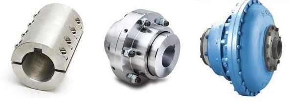
What Is a Coupling?
A coupling is a device that connects two shafts together. It transmits power from one to the other and is used to join rotating equipment. It can also allow for some degree of misalignment and end movement. It is used in mechanical engineering and manufacturing. To learn more about couplings, read this article. Mechanical connection between two objectsThe present invention relates to a method and assembly for forming a mechanical connection between two objects. The methods of this invention are suitable for connecting both solid and hollow objects. For example, the method can be used to make mechanical connections between two cylinders. This method is particularly useful for connecting two cylinders that are positioned near each other.
Absorbs vibration
A coupling insert is a part of a vehicle’s drivetrain that absorbs vibrations. These inserts are designed to prevent couplings from moving out of phase. However, the coupling inserts themselves can wear out and need to be replaced. Universal joints are an alternative if the coupling is out of phase by more than one degree. In addition, internal bearings in the coupling need to be lubricated and replaced when they begin to show signs of wear.
Another embodiment of the invention includes a flexible coupling 25 that includes rearwardly-extending lugs that extend toward the coupling member 23. These lugs interdigitate with corresponding lugs on the coupling member 23. They are spaced circumferentially. A first elastic member 28 is interposed between lugs 26 and 27, and is adapted to yield in a counterclockwise direction. As a result, it absorbs torsional vibrations.
Blocks heat transfer
Thermal coupling occurs when a solid block is thermally coupled to the air or fluid passing through it. The amount of heat transferred through a solid block depends on the heat transfer coefficients of the materials. This paper presents a numerical model to understand how heat transfers through different block materials. This work also describes the thermal resistance network for a one-dimensional block.
In some cases, thermal coupling increases the heat transfer mechanism. As illustrated in FIG. 1D, a heatpipe coupler 112 couples two heatpipes 110-1 and 110-2. This configuration allows the pipes to be coupled to the heat source and to the condenser. In addition, the heat pipe couplers may have bellows at the ends to help facilitate linear motion.
Thermal coupling is achieved by ensuring that at least one block is made of a material with a lower thermal expansion coefficient than the annulus. Ideally, the block’s mean thermal expansion coefficient is at least twenty percent lower than the annulus’s mean thermal expansion coefficient. This ensures that the thermal coupling between the two parts is as efficient as possible.
Another type of thermal coupling is achieved by using flexible elements. These are often washers or springs. These components allow the blocks to maintain physical contact with the post 55, which means that the heat transfer is more efficient even at higher temperatures. The flexibility of these elements also makes it possible to choose an element that will not impede assembly.
Protects rotating equipment
A reliable, long-lasting coupling system can reduce the risk of damage to rotating equipment. Designed to protect against torque overload and wear, Voith torque-limiting couplings provide outstanding safety and reliability. As a result, they can deliver maximum performance and minimize equipment downtime. In addition to their long-term benefits, these solutions are ideal for applications where safety and reliability are of paramount importance.
A good coupling provides many advantages, including the ability to transmit power, compensate for axial movement, and absorb shock. It is essential to choose the proper coupling for your application based on the basic conditions of your rotating equipment. For example, if you have two shafts with parallel rotation axes, you should choose a parallel coupling. Otherwise, you should use an angular coupling.
Torque-limiting couplings can also provide protection for rotating equipment by disengaging at a specific torque level. This protects the drive shaft from undergoing catastrophic failure. Torque limiters are particularly helpful for high-value equipment. By preventing catastrophic failure, you can avoid expensive repairs and minimize equipment downtime.
Coupling guards are easy to install and provide effective protection for rotating equipment. These covers are made of sheet metal bent to fit over the shaft. They are durable and easy to remove when necessary. This type of guard can prevent employees from catching their hands, tools, or loose clothing on motor coupling components.
editor by czh 2023-03-20