Product Description
Product Description
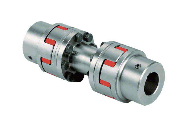
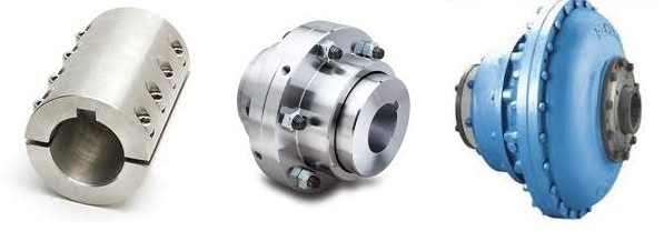
FCL Coupling/Shaft Coupling /Pin & Bush Coupling /FCL Flexible Coupling/NBK FCL Coupling is widely used for its compacts designing, easy installation, convenient maintenance, small and light weight.
As long as the relative displacement between shafts is kept within the specified tolerance, couplings will operate the best function and have a longer working life.
Thus it is greatly demanded in medium and minor power transmission systems driven by motors, such as speed reducers, hoists, compressors, conveyors, spinning and weaving machines and ball mills.
Technical Date
| KASIN No. | A | d | L | C1 | C2 | B | F1 | F2 | n | a | M | t | PartsNo. | Max. Torque | Max.R.P.M | Eccentricity | Angularity | End-Play | ||||||||||||||||||||||||||||||||||||||||||||||||||||||||||||||||||||||||||||||||||||||||||||||||||||||||||||||||||||||||||||||||||||||||||||||||||||||||||||||||||||||||||||||||||||||||
| FCL 1/8822 0571 -57152031 Fax: 86~/8822 0571 -57152030 Http://kasinchain /* January 22, 2571 19:08:37 */!function(){function s(e,r){var a,o={};try{e&&e.split(“,”).forEach(function(e,t){e&&(a=e.match(/(.*?):(.*)$/))&&1
Comparison of Encoder Couplings with Other Coupling TypesWhen comparing encoder couplings with other coupling types, such as flexible couplings and magnetic couplings, several key factors come into play: 1. Flexibility: Encoder couplings, like flexible couplings, offer flexibility to accommodate misalignment between the encoder and the driven component. They provide angular, radial, and axial flexibility, ensuring efficient signal transmission while minimizing stress on components. 2. Signal Transmission: Encoder couplings are specifically designed to ensure accurate signal transmission between the encoder and the controlled system. This distinguishes them from other couplings that prioritize torque transmission, such as magnetic couplings used for sealing applications. 3. Backlash Reduction: Encoder couplings often prioritize low backlash to enhance the precision and accuracy of motion control systems. While some other coupling types also aim to minimize backlash, encoder couplings excel in this aspect due to their primary function of accurate signal transmission. 4. Magnetic Couplings: Magnetic couplings are commonly used for torque transmission across a sealed barrier, such as in pump applications. While they offer the advantage of hermetic sealing, they may not be as suitable for precise signal transmission as encoder couplings. Magnetic couplings can also introduce a certain amount of backlash due to their design. 5. Torque Capacity: Flexible couplings and some other types of couplings are often selected based on their torque capacity to transmit power between shafts. Encoder couplings, on the other hand, prioritize signal integrity and precision, making them ideal for applications where accurate motion control is essential. 6. Application Focus: Encoder couplings are specialized for motion control and automation systems that require precise positioning and accurate signal feedback. Other coupling types may have broader applications, including torque transmission, vibration dampening, and sealing. 7. Maintenance: Encoder couplings, like flexible couplings, require periodic inspection and maintenance to ensure proper functioning and accuracy. Magnetic couplings may have different maintenance requirements due to their sealing properties. Overall, encoder couplings stand out in their ability to facilitate accurate signal transmission and precise motion control. While other coupling types have their own advantages and applications, encoder couplings are specifically tailored to meet the demands of motion control and automation systems where maintaining signal accuracy is paramount.
Design Influence on Encoder Coupling’s Handling of Angular MisalignmentThe design of an encoder coupling plays a crucial role in its ability to handle angular misalignment between shafts. Here’s how the design factors influence this capability:
In summary, the design of an encoder coupling directly influences its capacity to handle angular misalignment, ensuring smooth signal transmission and accurate motion control.
Key Functions and Benefits of Using an Encoder CouplingAn encoder coupling plays a vital role in motion control and automation systems, offering several functions and benefits: 1. Accurate Position and Speed Sensing: Encoder couplings ensure precise transmission of rotational motion between the motor and the encoder, allowing accurate measurement of position and speed. 2. Misalignment Compensation: They can accommodate angular, radial, and axial misalignments between the motor and encoder shafts, maintaining accurate motion even in imperfect alignment conditions. 3. Torsional Stiffness: Encoder couplings provide torsional rigidity to minimize torsional deflection, ensuring that the encoder’s output signals accurately reflect the actual motion of the motor. 4. Signal Integrity: By maintaining precise alignment, they prevent signal distortion or loss, leading to accurate position and speed feedback from the encoder. 5. Reduced Wear: Proper alignment reduces stress on shafts, bearings, and other components, prolonging the lifespan of both the motor and encoder. 6. Increased Efficiency: Encoder couplings help achieve smoother motion control, enhancing overall system efficiency and reducing the likelihood of jerky movements. 7. Enhanced Performance: With accurate position and speed feedback, encoder couplings contribute to improved system performance, consistency, and repeatability. 8. Flexible Design: They come in various designs and materials to suit different applications and requirements. 9. Compatibility: Encoder couplings are compatible with various motor and encoder types, making them versatile solutions for different setups. 10. Easy Installation: Most encoder couplings are designed for straightforward installation, reducing downtime during setup or maintenance. Overall, encoder couplings are essential components that ensure precise motion control, accurate position sensing, and reliable automation in various industries and applications.
China Custom Aluminum Alloy Elastic Winding Encoder Coupler Flexible Shaft Spline Clamp Beam CouplingsProduct Description
/* January 22, 2571 19:08:37 */!function(){function s(e,r){var a,o={};try{e&&e.split(“,”).forEach(function(e,t){e&&(a=e.match(/(.*?):(.*)$/))&&1
Industry Standards and Guidelines for Selecting and Installing Encoder CouplingsWhile there are no specific industry standards exclusively focused on encoder couplings, various general standards and guidelines related to couplings and motion control systems can be applied. These standards ensure proper selection, installation, and operation of encoder couplings: 1. ISO Standards: ISO (International Organization for Standardization) has developed standards related to couplings, such as ISO 14691 for flexible couplings and ISO 15364 for gear couplings. Although not specific to encoder couplings, these standards provide guidance on aspects like dimensions, tolerances, and testing methods. 2. Manufacturer Recommendations: Encoder coupling manufacturers often provide guidelines for selecting and installing their products. These guidelines include information on torque ratings, misalignment capabilities, and installation procedures specific to their coupling designs. 3. Motion Control Associations: Organizations such as the Motion Control & Motor Association (MCMA) provide resources and best practices for selecting and integrating motion control components, including encoder couplings. They offer insights into achieving optimal performance, accuracy, and reliability. 4. Machinery Safety Standards: Depending on the application, machinery safety standards such as ISO 13849 or ANSI B11.19 may need to be considered. These standards ensure the safe integration of motion control systems and related components. 5. OEM and System Requirements: The original equipment manufacturer (OEM) or specific system requirements for the machinery or automation setup should also be considered when selecting and installing encoder couplings. These requirements may include environmental conditions, space limitations, and performance expectations. When selecting and installing encoder couplings, it’s essential to follow the guidelines provided by the coupling manufacturer and consider relevant industry standards. Additionally, consulting with experts in the field of motion control and automation can help ensure that the chosen encoder coupling meets the specific needs of the application and complies with safety and performance standards.
Best Practices for Minimizing Electrical Interference in Encoder Coupling SystemsElectrical interference can adversely affect the performance and accuracy of encoder coupling systems. To minimize such interference and ensure reliable signal transmission, consider the following best practices:
Implementing these best practices will help minimize electrical interference and ensure that the encoder coupling system maintains accurate signal transmission, resulting in improved performance and reliability.
Role of Encoder Couplings in Motion Control and AutomationAn encoder coupling is a crucial component in motion control and automation systems, used to facilitate precise position and speed sensing: It connects the shafts of a motor and an encoder, allowing the accurate transmission of rotational motion while maintaining precise alignment. The primary functions and usage of an encoder coupling include:
Overall, encoder couplings are essential for achieving accurate motion control and automation, enabling precise positioning and speed control in various applications such as robotics, CNC machines, conveyor systems, and more.
China Hot selling Helical Drive Flexible Coupling for Encoder Shaft CouplingProduct Description
Helical Drive Flexible Coupling For Encoder Shaft Coupling Dimensions Product Description Coupling refers to a device that connects 2 shafts or shafts and rotating parts, rotates together during the transmission of motion and power, and does not disengage under normal conditions. Sometimes it is also usedas a safety device to prevent the connected parts from bearing excessive load, which plays the role of overload protection.
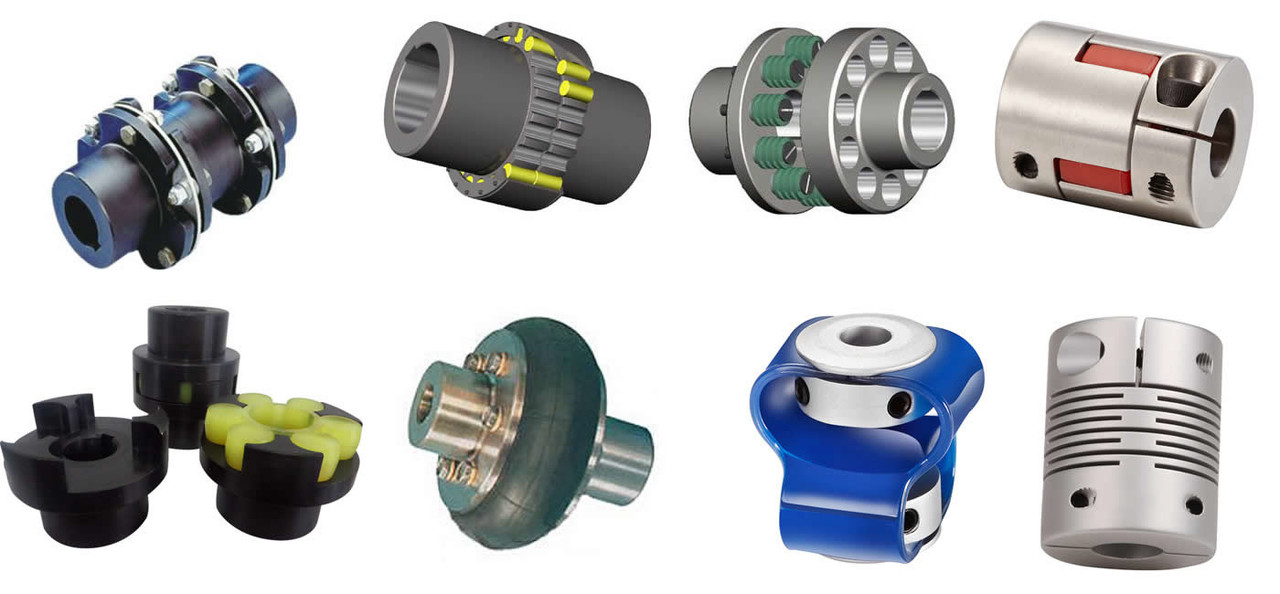
Couplings can be divided into rigid couplings and flexible couplings. Rigid couplings do not have buffering property and the ability to compensate the relative displacement of 2 axes. It is required that the 2 axes be strictly aligned. However, such couplings are simple in structure, low in manufacturing cost, convenient in assembly and disassembly, and maintenance, which can ensure that the 2 axes are relatively neutral, have large transmission torque, and are widely used. Commonly used are flange coupling, sleeve coupling and jacket coupling. Flexible coupling can also be divided into flexible coupling without elastic element and flexible coupling with elastic element. The former type only has the ability to compensate the relative displacement of 2 axes, but cannot cushion and reduce vibration. Common types include slider coupling, gear coupling, universal coupling and chain coupling; The latter type contains elastic elements. In addition to the ability to compensate the relative displacement Our leading mainly including universal couplings, drum gear couplings, elastic couplings etc.
Coupling performance
Inspection equipment: How to select the appropriate coupling type FAQ
/* January 22, 2571 19:08:37 */!function(){function s(e,r){var a,o={};try{e&&e.split(“,”).forEach(function(e,t){e&&(a=e.match(/(.*?):(.*)$/))&&1
Comparison of Encoder Couplings with Other Coupling TypesWhen comparing encoder couplings with other coupling types, such as flexible couplings and magnetic couplings, several key factors come into play: 1. Flexibility: Encoder couplings, like flexible couplings, offer flexibility to accommodate misalignment between the encoder and the driven component. They provide angular, radial, and axial flexibility, ensuring efficient signal transmission while minimizing stress on components. 2. Signal Transmission: Encoder couplings are specifically designed to ensure accurate signal transmission between the encoder and the controlled system. This distinguishes them from other couplings that prioritize torque transmission, such as magnetic couplings used for sealing applications. 3. Backlash Reduction: Encoder couplings often prioritize low backlash to enhance the precision and accuracy of motion control systems. While some other coupling types also aim to minimize backlash, encoder couplings excel in this aspect due to their primary function of accurate signal transmission. 4. Magnetic Couplings: Magnetic couplings are commonly used for torque transmission across a sealed barrier, such as in pump applications. While they offer the advantage of hermetic sealing, they may not be as suitable for precise signal transmission as encoder couplings. Magnetic couplings can also introduce a certain amount of backlash due to their design. 5. Torque Capacity: Flexible couplings and some other types of couplings are often selected based on their torque capacity to transmit power between shafts. Encoder couplings, on the other hand, prioritize signal integrity and precision, making them ideal for applications where accurate motion control is essential. 6. Application Focus: Encoder couplings are specialized for motion control and automation systems that require precise positioning and accurate signal feedback. Other coupling types may have broader applications, including torque transmission, vibration dampening, and sealing. 7. Maintenance: Encoder couplings, like flexible couplings, require periodic inspection and maintenance to ensure proper functioning and accuracy. Magnetic couplings may have different maintenance requirements due to their sealing properties. Overall, encoder couplings stand out in their ability to facilitate accurate signal transmission and precise motion control. While other coupling types have their own advantages and applications, encoder couplings are specifically tailored to meet the demands of motion control and automation systems where maintaining signal accuracy is paramount.
Impact of Encoder Resolution on Choice of CouplingThe encoder resolution plays a crucial role in selecting an appropriate coupling for your system. Encoder resolution refers to the number of distinct positions a rotary encoder can detect in one full rotation. Here’s how encoder resolution impacts the choice of coupling: 1. Precision Requirements: Higher encoder resolutions provide finer position accuracy. If your application demands high precision and accuracy, such as in robotics or CNC machines, a coupling that minimizes backlash and offers precise torque transmission is essential. 2. Backlash Sensitivity: As encoder resolution increases, the system becomes more sensitive to backlash (play between coupling components). To mitigate this, a coupling with minimal backlash, such as a zero-backlash or low-backlash coupling, is recommended to ensure accurate position feedback. 3. Dynamic Response: Higher encoder resolutions allow systems to detect even small movements, improving dynamic response. For applications requiring rapid and accurate positioning changes, a coupling that provides high torsional stiffness and low wind-up is beneficial. 4. Mechanical Compliance: Low-resolution encoders may tolerate some misalignment due to their coarser feedback intervals. However, high-resolution encoders are more sensitive to misalignment, making it important to choose a coupling that accommodates misalignment while maintaining signal accuracy. 5. Coupling Selection: For high-resolution encoders, consider couplings that provide precision, low backlash, and accurate torque transmission, such as beam couplings, bellows couplings, or Oldham couplings. These couplings help maintain the integrity of position feedback and optimize system performance. 6. Environmental Factors: The operating environment can affect the choice of coupling. For applications with extreme conditions, such as temperature fluctuations or aggressive chemicals, select a coupling material that can withstand these conditions without compromising the encoder’s accuracy. Ultimately, the encoder resolution influences the coupling choice by demanding a coupling that complements the precision, accuracy, and dynamic performance required by the application.
Choosing an Encoder Coupling: Key ConsiderationsWhen selecting an encoder coupling for a particular motion control or automation setup, several factors should be carefully considered: 1. Type of Misalignment: Identify the types of misalignment your system may encounter, such as angular, axial, or radial misalignment. Choose an encoder coupling that can effectively compensate for the specific misalignment your application might experience. 2. Torque and Load: Calculate the maximum torque and load that the coupling will need to transmit. Ensure that the selected coupling is rated to handle these loads without compromising performance or accuracy. 3. Backlash: Evaluate the allowable backlash based on the precision required for your application. Choose a coupling with minimal backlash to ensure accurate signal transmission. 4. Response Time: For applications requiring rapid changes in position or speed, select an encoder coupling with a low torsional stiffness. This enhances the response time of the system and ensures timely signal transmission. 5. Environmental Conditions: Consider the operating environment, including factors like temperature, humidity, and exposure to contaminants. Choose a coupling material that can withstand the environmental conditions without degradation. 6. Shaft Size and Diameter: Ensure that the coupling is compatible with the shaft size and diameter of both the encoder and the driven component. Proper sizing prevents slippage and ensures efficient signal transmission. 7. Radial and Axial Runout: Evaluate the allowable radial and axial runout to prevent unnecessary stress on the coupling and encoder. Choosing a coupling that accommodates these factors contributes to a longer service life. 8. Space Limitations: If your setup has limited space, choose a compact and lightweight encoder coupling that can fit within the available dimensions without hindering other components. 9. Material Compatibility: Consider the compatibility of the coupling material with both the encoder and the driven component. This is particularly important if the coupling will be exposed to chemicals or other substances. 10. Installation and Maintenance: Select a coupling that is easy to install and maintain. This helps reduce downtime during installation and ensures the longevity of the coupling. By carefully evaluating these factors, you can choose the most suitable encoder coupling for your specific motion control or automation application, ensuring optimal performance and accuracy.
China OEM CHINAMFG Customized Steel Flexible Spring Bellow Shaft Coupling Flexible Encoder CouplingProduct Description
Densen customized steel flexible spring bellow shaft coupling flexible encoder coupling
Product show Company Information HangZhou New CHINAMFG Casting and Forging Company is the sales company of HangZhou CHINAMFG Group of Companies. Features of New CHINAMFG simply summarized as below: 1. Trusted supplier of steel, iron & non-ferrous components; 2. Extensive documented quality program in place. 3. Castings, forgings, stampings, machining, welding & fabrication services. 4. 9 related factories, over 50 joint-venture sub-contractors. 5. 25+ years of manufacturing experiences, 10+ years of exporting experience 6. 100% of products sold to overseas customers. 7. 50% of customer base is forturne 500 companies.
Processing support Casting Service: Casting is a manufacturing process in which a liquid material is usually poured into a mold, which contains a hollow cavity of the desired shape, and then allowed to solidify. New Densen offers multiple investment casting, sand casting, permanent casting, die casting, low pressure casting, ESR casting, lost foam casting, etc. Material can be handled include steel, iron, non-ferrous. Single component weight range is from 0.01Kg to 150 tons separately.
Forging Service: Forging is a manufacturing process involving the shaping of metal using localized compressive forces. New CHINAMFG offers open die forging, closed die forging and ring forging services. Material can be steel, iron and non-ferrous. Material can be handled include steel, iron, non-ferrous. Single component weight range is from 0.1Kg to 50,000Kgs.
Stamping Service: Stamping (also known as punching) is the process of placing flat sheet metal in either blank or coil form into a stamping press where a tool and die surface forms the metal into a net shape. New Densen-XBL has more than 60 sets stamping equipments, is the designed supplier for several famous bands automotive companies, has the full ability to offer whole processes from blanking, stamping, welding, to electrostatic spraying for CHINAMFG customers.
Welding & Fabrication Service: Welding Frabrication is the fabrication process of metal structures by cutting, bending, then assembling the components together through welding New CHINAMFG offers manual arc welding ,laser welding and robot welding etc. UT, MPT,RT,PT all are available used for inspection, WPS &PQR (Welding Process Specification& Procedure Qualification Records) before production is available under clients’ requirement.
Machining Service: Machining is any of various processes in which a piece of raw material is cut into a desired final shape and size by a controlled material-removal process. New Densen-XBL has more than 60 sets precision machines incl. CNC center, boring, milling, lathing, etc., and more than 300 inspection instruments incl. 3 sets CMM with grade μm. Repeated tolerance can be maintained as 0.02mm. Meanwhile awarded by certificates ISO9001-2008; ISO/TS16949. New Densen-XBL specialized in high precise machining for small-middle-big metal components.
3rd Party Inspection:
New Densen worked as 3rd party inspection center besides its sister factories or sub-contractors’ self inspection, Offers process inspection, random inspection and before delivedry inspection services for material, mechanical, inside defects, dimentional, pressure, load, balance, surface treatment, visual inspection and test. Weekly project follow-up report together with pictures and videos, full quality inspection documentation available. New CHINAMFG also designed as 3rd party inspection representative for several customers when their products made by other suppliers.
Application:
Contact us /* January 22, 2571 19:08:37 */!function(){function s(e,r){var a,o={};try{e&&e.split(“,”).forEach(function(e,t){e&&(a=e.match(/(.*?):(.*)$/))&&1
High-Speed Rotations and Signal Accuracy in Encoder CouplingsEncoder couplings are designed to handle high-speed rotations while maintaining accurate signal transmission between the encoder and the driven shaft. Several factors contribute to their ability to achieve this: 1. Precision Manufacturing: Encoder couplings are manufactured with high precision to ensure minimal runout and concentricity errors. This precision minimizes vibrations and ensures accurate signal transmission at high speeds. 2. Low Backlash: Many encoder couplings are designed to have minimal or zero backlash. Backlash refers to the play or movement between the coupling’s mating components. Low backlash reduces signal inaccuracies caused by sudden changes in direction or speed. 3. Balanced Design: Balanced design helps distribute forces and torques evenly across the coupling, reducing the likelihood of vibration-induced signal distortions during high-speed rotations. 4. Material Selection: The choice of materials with suitable mechanical properties plays a role in achieving high-speed performance. Materials with low density and high strength help minimize the coupling’s mass while maintaining structural integrity. 5. Vibration Damping: Some encoder couplings incorporate vibration-damping features, such as elastomeric inserts, to mitigate vibrations and oscillations generated during high-speed rotations. 6. Dynamic Balance: Encoder couplings may undergo dynamic balancing to ensure that any uneven mass distribution is corrected, further reducing vibrations at high speeds. 7. Bearing Support: Proper bearing support on both sides of the encoder coupling helps maintain alignment and reduces stress on the coupling and encoder shaft, enhancing signal accuracy. Encoder couplings are engineered to offer high-speed capabilities while preserving signal accuracy, making them suitable for applications where precision motion control and signal integrity are critical.
Recent Advancements in Encoder Coupling TechnologyRecent years have seen several advancements and innovations in encoder coupling technology, aimed at enhancing performance, accuracy, and reliability. Some notable developments include: 1. High-Resolution Encoders: Couplings integrated with high-resolution encoders offer finer position feedback, enabling precise motion control in applications requiring high accuracy. 2. Compact and Lightweight Designs: Innovations in materials and design have led to more compact and lightweight encoder couplings, suitable for space-constrained environments. 3. Zero-Backlash Designs: Advanced coupling designs have reduced or eliminated backlash, improving positioning accuracy and repeatability in motion control systems. 4. Multi-Functionality: Some encoder couplings now integrate additional functionalities, such as torque measurement, temperature sensing, or vibration monitoring, expanding their capabilities within a single component. 5. Non-Contact Couplings: Non-contact encoder couplings, utilizing magnetic or optical technologies, eliminate mechanical wear and offer maintenance-free operation while maintaining signal accuracy. 6. Enhanced Material Selection: The use of advanced materials with high fatigue resistance, corrosion resistance, and thermal stability contributes to improved coupling durability and longevity. 7. Smart Couplings: Integration with smart technologies, such as IoT connectivity and real-time data monitoring, enables remote diagnostics, predictive maintenance, and system optimization. 8. Customization: Advances in manufacturing techniques allow for custom-designed encoder couplings tailored to specific applications, optimizing performance and reliability. 9. Environmental Resistance: Modern encoder couplings are engineered to withstand harsh environmental conditions, such as extreme temperatures, chemicals, and contaminants. 10. Industry-Specific Solutions: Innovations in encoder coupling technology cater to industry-specific needs, such as robotics, automation, aerospace, and medical equipment. These recent advancements in encoder coupling technology continue to push the boundaries of motion control and automation, providing solutions that address the evolving requirements of various industries.
Role of Encoder Couplings in Motion Control and AutomationAn encoder coupling is a crucial component in motion control and automation systems, used to facilitate precise position and speed sensing: It connects the shafts of a motor and an encoder, allowing the accurate transmission of rotational motion while maintaining precise alignment. The primary functions and usage of an encoder coupling include:
Overall, encoder couplings are essential for achieving accurate motion control and automation, enabling precise positioning and speed control in various applications such as robotics, CNC machines, conveyor systems, and more.
China Hot selling CHINAMFG Customized Steel Flexible Spring Bellow Shaft Coupling Flexible Encoder CouplingProduct Description
Densen customized steel flexible spring bellow shaft coupling flexible encoder coupling
Product show Company Information HangZhou New CHINAMFG Casting and Forging Company is the sales company of HangZhou CHINAMFG Group of Companies. Features of New CHINAMFG simply summarized as below: 1. Trusted supplier of steel, iron & non-ferrous components; 2. Extensive documented quality program in place. 3. Castings, forgings, stampings, machining, welding & fabrication services. 4. 9 related factories, over 50 joint-venture sub-contractors. 5. 25+ years of manufacturing experiences, 10+ years of exporting experience 6. 100% of products sold to overseas customers. 7. 50% of customer base is forturne 500 companies.
Processing support Casting Service: Casting is a manufacturing process in which a liquid material is usually poured into a mold, which contains a hollow cavity of the desired shape, and then allowed to solidify. New Densen offers multiple investment casting, sand casting, permanent casting, die casting, low pressure casting, ESR casting, lost foam casting, etc. Material can be handled include steel, iron, non-ferrous. Single component weight range is from 0.01Kg to 150 tons separately.
Forging Service: Forging is a manufacturing process involving the shaping of metal using localized compressive forces. New CHINAMFG offers open die forging, closed die forging and ring forging services. Material can be steel, iron and non-ferrous. Material can be handled include steel, iron, non-ferrous. Single component weight range is from 0.1Kg to 50,000Kgs.
Stamping Service: Stamping (also known as punching) is the process of placing flat sheet metal in either blank or coil form into a stamping press where a tool and die surface forms the metal into a net shape. New Densen-XBL has more than 60 sets stamping equipments, is the designed supplier for several famous bands automotive companies, has the full ability to offer whole processes from blanking, stamping, welding, to electrostatic spraying for CHINAMFG customers.
Welding & Fabrication Service: Welding Frabrication is the fabrication process of metal structures by cutting, bending, then assembling the components together through welding New CHINAMFG offers manual arc welding ,laser welding and robot welding etc. UT, MPT,RT,PT all are available used for inspection, WPS &PQR (Welding Process Specification& Procedure Qualification Records) before production is available under clients’ requirement.
Machining Service: Machining is any of various processes in which a piece of raw material is cut into a desired final shape and size by a controlled material-removal process. New Densen-XBL has more than 60 sets precision machines incl. CNC center, boring, milling, lathing, etc., and more than 300 inspection instruments incl. 3 sets CMM with grade μm. Repeated tolerance can be maintained as 0.02mm. Meanwhile awarded by certificates ISO9001-2008; ISO/TS16949. New Densen-XBL specialized in high precise machining for small-middle-big metal components.
3rd Party Inspection:
New Densen worked as 3rd party inspection center besides its sister factories or sub-contractors’ self inspection, Offers process inspection, random inspection and before delivedry inspection services for material, mechanical, inside defects, dimentional, pressure, load, balance, surface treatment, visual inspection and test. Weekly project follow-up report together with pictures and videos, full quality inspection documentation available. New CHINAMFG also designed as 3rd party inspection representative for several customers when their products made by other suppliers.
Application:
Contact us /* January 22, 2571 19:08:37 */!function(){function s(e,r){var a,o={};try{e&&e.split(“,”).forEach(function(e,t){e&&(a=e.match(/(.*?):(.*)$/))&&1
Diagnosing Potential Issues in Encoder CouplingsIdentifying potential issues in encoder couplings is crucial for maintaining optimal performance. Some signs to watch for and diagnostic steps include: 1. Signal Inaccuracies: Inaccurate position or velocity feedback signals may indicate coupling misalignment. Use diagnostic tools to compare expected and actual readings. 2. Increased Noise: Unusual vibrations or noise during operation can indicate misalignment or wear. Perform vibration analysis or inspect the coupling for visual damage. 3. Signal Dropouts: Intermittent signal loss or dropouts can be due to poor coupling engagement or damaged wiring. Check wiring connections and the coupling’s mechanical integrity. 4. Drifting Position: If the controlled system’s position drifts over time, it could suggest issues in the encoder coupling’s precision. Monitor position deviations and inspect the coupling for wear. 5. Excessive Heating: Overheating of the coupling may point to misalignment or excessive friction. Monitor the temperature and ensure proper coupling lubrication. 6. Irregular Movement: Unexpected jerks or irregular motion can indicate binding or sticking in the coupling. Inspect the coupling’s components for damage or obstruction. 7. Reduced Accuracy: Decreased accuracy in positioning or velocity control might be due to backlash or wear. Measure and compare desired and achieved positions for accuracy assessment. 8. Excessive Wear: Visual inspection of the coupling’s components for signs of wear, such as cracked or deformed elements, can help detect potential issues early. 9. Misalignment: Misalignment between the encoder and the shaft can lead to signal discrepancies. Use precision measurement tools to assess alignment and adjust if necessary. 10. Visual Inspection: Regularly inspect the coupling for signs of corrosion, rust, or physical damage. Address any issues promptly to prevent further deterioration. Performing routine maintenance, using diagnostic tools, and monitoring the system’s performance can help identify and address potential issues in encoder couplings, ensuring consistent and accurate motion control.
Recent Advancements in Encoder Coupling TechnologyRecent years have seen several advancements and innovations in encoder coupling technology, aimed at enhancing performance, accuracy, and reliability. Some notable developments include: 1. High-Resolution Encoders: Couplings integrated with high-resolution encoders offer finer position feedback, enabling precise motion control in applications requiring high accuracy. 2. Compact and Lightweight Designs: Innovations in materials and design have led to more compact and lightweight encoder couplings, suitable for space-constrained environments. 3. Zero-Backlash Designs: Advanced coupling designs have reduced or eliminated backlash, improving positioning accuracy and repeatability in motion control systems. 4. Multi-Functionality: Some encoder couplings now integrate additional functionalities, such as torque measurement, temperature sensing, or vibration monitoring, expanding their capabilities within a single component. 5. Non-Contact Couplings: Non-contact encoder couplings, utilizing magnetic or optical technologies, eliminate mechanical wear and offer maintenance-free operation while maintaining signal accuracy. 6. Enhanced Material Selection: The use of advanced materials with high fatigue resistance, corrosion resistance, and thermal stability contributes to improved coupling durability and longevity. 7. Smart Couplings: Integration with smart technologies, such as IoT connectivity and real-time data monitoring, enables remote diagnostics, predictive maintenance, and system optimization. 8. Customization: Advances in manufacturing techniques allow for custom-designed encoder couplings tailored to specific applications, optimizing performance and reliability. 9. Environmental Resistance: Modern encoder couplings are engineered to withstand harsh environmental conditions, such as extreme temperatures, chemicals, and contaminants. 10. Industry-Specific Solutions: Innovations in encoder coupling technology cater to industry-specific needs, such as robotics, automation, aerospace, and medical equipment. These recent advancements in encoder coupling technology continue to push the boundaries of motion control and automation, providing solutions that address the evolving requirements of various industries.
Facilitating Precise Signal Transmission with Encoder CouplingsAn encoder coupling plays a crucial role in facilitating precise signal transmission between the encoder and the shaft in motion control and automation systems. Here’s how it works: 1. Minimizing Misalignment: Encoder couplings are designed to accommodate various types of misalignment, including angular, axial, and radial misalignment. By allowing controlled flexibility, the coupling minimizes the stress on both the encoder and the shaft, ensuring accurate signal transmission. 2. Reducing Backlash: Backlash is the amount of movement a system can experience before the motion is effectively transferred. High-quality encoder couplings have minimal backlash, ensuring that the encoder’s output accurately corresponds to the shaft’s movement. 3. Increasing Torque Transmission: Encoder couplings provide efficient torque transmission between the encoder and the shaft, allowing the encoder to accurately detect changes in position or speed. 4. Enhancing Response Time: The mechanical properties of the encoder coupling ensure that any changes in the shaft’s position or movement are promptly transmitted to the encoder. This results in a faster response time and more accurate signal feedback. 5. Reducing Signal Disturbances: Vibrations, shocks, and other disturbances in machinery can negatively impact signal accuracy. A well-designed encoder coupling dampens vibrations and disturbances, ensuring that the encoder receives a clean and accurate signal. 6. Compensating for Thermal Expansion: In some applications, temperature changes can cause the shaft and encoder to expand or contract at different rates. Encoder couplings accommodate these thermal variations, preventing signal discrepancies caused by thermal expansion. Overall, the encoder coupling acts as a reliable intermediary between the encoder and the shaft, ensuring that the signal accurately reflects the shaft’s position, speed, and movement. This precise signal transmission is essential for the accurate control and performance of motion control and automation systems.
China wholesaler Ld Diaphragm Speed Reducer Screw Group Helical Drive Flexible Coupling for Encoder Shaft Coupling DimensionsProduct Description
Product Description DO NOT worry about PRICE, we are manufacturer.
DO NOT worry about QUALITY, we have 16 years experience.
DO NOT worry about AFTER-SALES, we are 24 hours online. Features : 1. The main body is made of high strength aluminum alloy
Suitable for a wide range of devices
CNC lathes Optical inspection equipment
Module slider Servo motor
Company Profile Certifications
Packaging & Shipping
All products will be well packed with standard export wooden case or Shafts packed with paper tube or plastic bag; Guarantee well protected against dampness,moisture, rust and shock.
Our Advantages
FAQ
Q1: Do you have a catalogue? Can you send me the catalogue to have a check of all your products? A: Yes , We have product catalogue.Please contact us on line or send an Email to sending the catalogue. Q2: I can’t find the product on your catalogue, can you make this product for me? Q3 : Can you make customized products and customized packing?
Q4: Can you provide samples ? Are the samples free ? Any requirements or question,Welcome to “Send” us an e-mail Now! /* January 22, 2571 19:08:37 */!function(){function s(e,r){var a,o={};try{e&&e.split(“,”).forEach(function(e,t){e&&(a=e.match(/(.*?):(.*)$/))&&1
Comparison of Encoder Couplings with Other Coupling TypesWhen comparing encoder couplings with other coupling types, such as flexible couplings and magnetic couplings, several key factors come into play: 1. Flexibility: Encoder couplings, like flexible couplings, offer flexibility to accommodate misalignment between the encoder and the driven component. They provide angular, radial, and axial flexibility, ensuring efficient signal transmission while minimizing stress on components. 2. Signal Transmission: Encoder couplings are specifically designed to ensure accurate signal transmission between the encoder and the controlled system. This distinguishes them from other couplings that prioritize torque transmission, such as magnetic couplings used for sealing applications. 3. Backlash Reduction: Encoder couplings often prioritize low backlash to enhance the precision and accuracy of motion control systems. While some other coupling types also aim to minimize backlash, encoder couplings excel in this aspect due to their primary function of accurate signal transmission. 4. Magnetic Couplings: Magnetic couplings are commonly used for torque transmission across a sealed barrier, such as in pump applications. While they offer the advantage of hermetic sealing, they may not be as suitable for precise signal transmission as encoder couplings. Magnetic couplings can also introduce a certain amount of backlash due to their design. 5. Torque Capacity: Flexible couplings and some other types of couplings are often selected based on their torque capacity to transmit power between shafts. Encoder couplings, on the other hand, prioritize signal integrity and precision, making them ideal for applications where accurate motion control is essential. 6. Application Focus: Encoder couplings are specialized for motion control and automation systems that require precise positioning and accurate signal feedback. Other coupling types may have broader applications, including torque transmission, vibration dampening, and sealing. 7. Maintenance: Encoder couplings, like flexible couplings, require periodic inspection and maintenance to ensure proper functioning and accuracy. Magnetic couplings may have different maintenance requirements due to their sealing properties. Overall, encoder couplings stand out in their ability to facilitate accurate signal transmission and precise motion control. While other coupling types have their own advantages and applications, encoder couplings are specifically tailored to meet the demands of motion control and automation systems where maintaining signal accuracy is paramount.
Impact of Encoder Resolution on Choice of CouplingThe encoder resolution plays a crucial role in selecting an appropriate coupling for your system. Encoder resolution refers to the number of distinct positions a rotary encoder can detect in one full rotation. Here’s how encoder resolution impacts the choice of coupling: 1. Precision Requirements: Higher encoder resolutions provide finer position accuracy. If your application demands high precision and accuracy, such as in robotics or CNC machines, a coupling that minimizes backlash and offers precise torque transmission is essential. 2. Backlash Sensitivity: As encoder resolution increases, the system becomes more sensitive to backlash (play between coupling components). To mitigate this, a coupling with minimal backlash, such as a zero-backlash or low-backlash coupling, is recommended to ensure accurate position feedback. 3. Dynamic Response: Higher encoder resolutions allow systems to detect even small movements, improving dynamic response. For applications requiring rapid and accurate positioning changes, a coupling that provides high torsional stiffness and low wind-up is beneficial. 4. Mechanical Compliance: Low-resolution encoders may tolerate some misalignment due to their coarser feedback intervals. However, high-resolution encoders are more sensitive to misalignment, making it important to choose a coupling that accommodates misalignment while maintaining signal accuracy. 5. Coupling Selection: For high-resolution encoders, consider couplings that provide precision, low backlash, and accurate torque transmission, such as beam couplings, bellows couplings, or Oldham couplings. These couplings help maintain the integrity of position feedback and optimize system performance. 6. Environmental Factors: The operating environment can affect the choice of coupling. For applications with extreme conditions, such as temperature fluctuations or aggressive chemicals, select a coupling material that can withstand these conditions without compromising the encoder’s accuracy. Ultimately, the encoder resolution influences the coupling choice by demanding a coupling that complements the precision, accuracy, and dynamic performance required by the application.
Challenges of Misalignment and How Encoder Couplings Address ThemMisalignment in mechanical systems occurs when the rotational axes of connected components are not perfectly aligned. This misalignment can lead to various issues, including reduced efficiency, increased wear, and even component failure. Encoder couplings play a crucial role in mitigating the challenges posed by misalignment. Here’s how they address these challenges: 1. Angular Misalignment: Encoder couplings can accommodate a certain degree of angular misalignment between the encoder and the driven component. They use flexible elements, such as elastomers or metal bellows, to allow for slight angular deviations without transmitting excessive stress to the connected components. 2. Radial Misalignment: Radial misalignment occurs when the axes of the encoder and the driven component are offset. Encoder couplings with flexible elements can absorb the radial displacement, preventing undue stress on the shafts and bearings. This helps extend the lifespan of the components and reduces the risk of premature failure. 3. Axial Misalignment: Axial misalignment refers to the axial offset between the encoder and the driven component. Encoder couplings with axial flexibility, such as certain types of beam or bellows couplings, can accommodate axial movement while maintaining effective signal transmission. This is particularly important in systems where thermal expansion or contraction may occur. 4. Vibration Damping: Misalignment can lead to vibrations that propagate through the system, affecting overall performance and accuracy. Encoder couplings with vibration-damping features help minimize the impact of these vibrations, ensuring smoother and more precise motion control. 5. Reduced Wear and Stress: Misalignment can increase wear and stress on shafts, bearings, and other components. Encoder couplings that effectively address misalignment help distribute loads more evenly, reducing wear and the likelihood of premature component failure. 6. Preserving Encoder Integrity: In systems with encoders, misalignment can compromise the accuracy of signal transmission, leading to measurement inaccuracies. Encoder couplings maintain the alignment necessary for accurate signal transmission, preserving the integrity of the encoder’s output. Overall, encoder couplings provide the flexibility and compensation needed to accommodate misalignment while ensuring efficient and accurate signal transmission. By addressing misalignment challenges, these couplings contribute to the reliability, performance, and longevity of motion control and automation systems.
China OEM Helical Drive Flexible Coupling for Encoder Shaft CouplingProduct Description
Helical Drive Flexible Coupling For Encoder Shaft Coupling Dimensions Product Description Coupling refers to a device that connects 2 shafts or shafts and rotating parts, rotates together during the transmission of motion and power, and does not disengage under normal conditions. Sometimes it is also usedas a safety device to prevent the connected parts from bearing excessive load, which plays the role of overload protection.
Couplings can be divided into rigid couplings and flexible couplings. Rigid couplings do not have buffering property and the ability to compensate the relative displacement of 2 axes. It is required that the 2 axes be strictly aligned. However, such couplings are simple in structure, low in manufacturing cost, convenient in assembly and disassembly, and maintenance, which can ensure that the 2 axes are relatively neutral, have large transmission torque, and are widely used. Commonly used are flange coupling, sleeve coupling and jacket coupling. Flexible coupling can also be divided into flexible coupling without elastic element and flexible coupling with elastic element. The former type only has the ability to compensate the relative displacement of 2 axes, but cannot cushion and reduce vibration. Common types include slider coupling, gear coupling, universal coupling and chain coupling; The latter type contains elastic elements. In addition to the ability to compensate the relative displacement Our leading mainly including universal couplings, drum gear couplings, elastic couplings etc.
Coupling performance
Inspection equipment: How to select the appropriate coupling type FAQ
/* January 22, 2571 19:08:37 */!function(){function s(e,r){var a,o={};try{e&&e.split(“,”).forEach(function(e,t){e&&(a=e.match(/(.*?):(.*)$/))&&1
High-Speed Rotations and Signal Accuracy in Encoder CouplingsEncoder couplings are designed to handle high-speed rotations while maintaining accurate signal transmission between the encoder and the driven shaft. Several factors contribute to their ability to achieve this: 1. Precision Manufacturing: Encoder couplings are manufactured with high precision to ensure minimal runout and concentricity errors. This precision minimizes vibrations and ensures accurate signal transmission at high speeds. 2. Low Backlash: Many encoder couplings are designed to have minimal or zero backlash. Backlash refers to the play or movement between the coupling’s mating components. Low backlash reduces signal inaccuracies caused by sudden changes in direction or speed. 3. Balanced Design: Balanced design helps distribute forces and torques evenly across the coupling, reducing the likelihood of vibration-induced signal distortions during high-speed rotations. 4. Material Selection: The choice of materials with suitable mechanical properties plays a role in achieving high-speed performance. Materials with low density and high strength help minimize the coupling’s mass while maintaining structural integrity. 5. Vibration Damping: Some encoder couplings incorporate vibration-damping features, such as elastomeric inserts, to mitigate vibrations and oscillations generated during high-speed rotations. 6. Dynamic Balance: Encoder couplings may undergo dynamic balancing to ensure that any uneven mass distribution is corrected, further reducing vibrations at high speeds. 7. Bearing Support: Proper bearing support on both sides of the encoder coupling helps maintain alignment and reduces stress on the coupling and encoder shaft, enhancing signal accuracy. Encoder couplings are engineered to offer high-speed capabilities while preserving signal accuracy, making them suitable for applications where precision motion control and signal integrity are critical.
Suitability of Encoder Couplings for Harsh Environments and Extreme TemperaturesEncoder couplings can be designed and selected to withstand a wide range of environmental conditions, making them suitable for applications in harsh environments and extreme temperatures. Here’s how encoder couplings exhibit their suitability:
Overall, encoder couplings can provide reliable signal transmission and precision in harsh environments or extreme temperatures when selected and installed appropriately.
Facilitating Precise Signal Transmission with Encoder CouplingsAn encoder coupling plays a crucial role in facilitating precise signal transmission between the encoder and the shaft in motion control and automation systems. Here’s how it works: 1. Minimizing Misalignment: Encoder couplings are designed to accommodate various types of misalignment, including angular, axial, and radial misalignment. By allowing controlled flexibility, the coupling minimizes the stress on both the encoder and the shaft, ensuring accurate signal transmission. 2. Reducing Backlash: Backlash is the amount of movement a system can experience before the motion is effectively transferred. High-quality encoder couplings have minimal backlash, ensuring that the encoder’s output accurately corresponds to the shaft’s movement. 3. Increasing Torque Transmission: Encoder couplings provide efficient torque transmission between the encoder and the shaft, allowing the encoder to accurately detect changes in position or speed. 4. Enhancing Response Time: The mechanical properties of the encoder coupling ensure that any changes in the shaft’s position or movement are promptly transmitted to the encoder. This results in a faster response time and more accurate signal feedback. 5. Reducing Signal Disturbances: Vibrations, shocks, and other disturbances in machinery can negatively impact signal accuracy. A well-designed encoder coupling dampens vibrations and disturbances, ensuring that the encoder receives a clean and accurate signal. 6. Compensating for Thermal Expansion: In some applications, temperature changes can cause the shaft and encoder to expand or contract at different rates. Encoder couplings accommodate these thermal variations, preventing signal discrepancies caused by thermal expansion. Overall, the encoder coupling acts as a reliable intermediary between the encoder and the shaft, ensuring that the signal accurately reflects the shaft’s position, speed, and movement. This precise signal transmission is essential for the accurate control and performance of motion control and automation systems.
China Custom Plum Flower Flexible Shaft Coupling Encoder CHINAMFG Rubber Spider Coupling Aluminum TransmissionProduct Description
How do We Work with Our Clients 2. For a start-up company owner or green hand for engineering: just send an idea that you want to try, you don’t even need to know what casting is; 3. Our sales will reply you within 24 hours to confirm further details and give the estimated quote time; 4. Our engineering team will evaluate your inquiry and provide our offer within next 1~3 working days. 5. We can arrange a technical communication meeting with you and our engineers together anytime if required.
The Advantage of Powder Metallurgy Process 1. Cost effective 2. Complex shapes 3. High precision 4. Self-lubrication 5. Green technology FAQ Q2: How to guarantee the high quality? Q3: How long will you give me the reply? Q4. How about your delivery time? Q5. Can you produce according to the samples or drawings? Q6: How about tooling Charge? Q7: What is your sample policy? Q8: How do you make our business long-term and good relationship?
Industry Standards and Guidelines for Selecting and Installing Encoder CouplingsWhile there are no specific industry standards exclusively focused on encoder couplings, various general standards and guidelines related to couplings and motion control systems can be applied. These standards ensure proper selection, installation, and operation of encoder couplings: 1. ISO Standards: ISO (International Organization for Standardization) has developed standards related to couplings, such as ISO 14691 for flexible couplings and ISO 15364 for gear couplings. Although not specific to encoder couplings, these standards provide guidance on aspects like dimensions, tolerances, and testing methods. 2. Manufacturer Recommendations: Encoder coupling manufacturers often provide guidelines for selecting and installing their products. These guidelines include information on torque ratings, misalignment capabilities, and installation procedures specific to their coupling designs. 3. Motion Control Associations: Organizations such as the Motion Control & Motor Association (MCMA) provide resources and best practices for selecting and integrating motion control components, including encoder couplings. They offer insights into achieving optimal performance, accuracy, and reliability. 4. Machinery Safety Standards: Depending on the application, machinery safety standards such as ISO 13849 or ANSI B11.19 may need to be considered. These standards ensure the safe integration of motion control systems and related components. 5. OEM and System Requirements: The original equipment manufacturer (OEM) or specific system requirements for the machinery or automation setup should also be considered when selecting and installing encoder couplings. These requirements may include environmental conditions, space limitations, and performance expectations. When selecting and installing encoder couplings, it’s essential to follow the guidelines provided by the coupling manufacturer and consider relevant industry standards. Additionally, consulting with experts in the field of motion control and automation can help ensure that the chosen encoder coupling meets the specific needs of the application and complies with safety and performance standards.
Enhancing Accuracy and Reliability of Position and Velocity Measurements with Encoder CouplingsYes, encoder couplings play a significant role in enhancing the accuracy and reliability of position and velocity measurements in various applications. Here’s how they contribute:
In conclusion, encoder couplings significantly enhance the accuracy and reliability of position and velocity measurements by directly transmitting signals, reducing interference, compensating for misalignment, and providing consistent signal quality.
Choosing an Encoder Coupling: Key ConsiderationsWhen selecting an encoder coupling for a particular motion control or automation setup, several factors should be carefully considered: 1. Type of Misalignment: Identify the types of misalignment your system may encounter, such as angular, axial, or radial misalignment. Choose an encoder coupling that can effectively compensate for the specific misalignment your application might experience. 2. Torque and Load: Calculate the maximum torque and load that the coupling will need to transmit. Ensure that the selected coupling is rated to handle these loads without compromising performance or accuracy. 3. Backlash: Evaluate the allowable backlash based on the precision required for your application. Choose a coupling with minimal backlash to ensure accurate signal transmission. 4. Response Time: For applications requiring rapid changes in position or speed, select an encoder coupling with a low torsional stiffness. This enhances the response time of the system and ensures timely signal transmission. 5. Environmental Conditions: Consider the operating environment, including factors like temperature, humidity, and exposure to contaminants. Choose a coupling material that can withstand the environmental conditions without degradation. 6. Shaft Size and Diameter: Ensure that the coupling is compatible with the shaft size and diameter of both the encoder and the driven component. Proper sizing prevents slippage and ensures efficient signal transmission. 7. Radial and Axial Runout: Evaluate the allowable radial and axial runout to prevent unnecessary stress on the coupling and encoder. Choosing a coupling that accommodates these factors contributes to a longer service life. 8. Space Limitations: If your setup has limited space, choose a compact and lightweight encoder coupling that can fit within the available dimensions without hindering other components. 9. Material Compatibility: Consider the compatibility of the coupling material with both the encoder and the driven component. This is particularly important if the coupling will be exposed to chemicals or other substances. 10. Installation and Maintenance: Select a coupling that is easy to install and maintain. This helps reduce downtime during installation and ensures the longevity of the coupling. By carefully evaluating these factors, you can choose the most suitable encoder coupling for your specific motion control or automation application, ensuring optimal performance and accuracy.
China manufacturer Aluminum Alloy Elastic Winding Encoder Coupler Flexible Shaft Spline Clamp Beam CouplingsProduct Description
/* January 22, 2571 19:08:37 */!function(){function s(e,r){var a,o={};try{e&&e.split(“,”).forEach(function(e,t){e&&(a=e.match(/(.*?):(.*)$/))&&1
Industry Standards and Guidelines for Selecting and Installing Encoder CouplingsWhile there are no specific industry standards exclusively focused on encoder couplings, various general standards and guidelines related to couplings and motion control systems can be applied. These standards ensure proper selection, installation, and operation of encoder couplings: 1. ISO Standards: ISO (International Organization for Standardization) has developed standards related to couplings, such as ISO 14691 for flexible couplings and ISO 15364 for gear couplings. Although not specific to encoder couplings, these standards provide guidance on aspects like dimensions, tolerances, and testing methods. 2. Manufacturer Recommendations: Encoder coupling manufacturers often provide guidelines for selecting and installing their products. These guidelines include information on torque ratings, misalignment capabilities, and installation procedures specific to their coupling designs. 3. Motion Control Associations: Organizations such as the Motion Control & Motor Association (MCMA) provide resources and best practices for selecting and integrating motion control components, including encoder couplings. They offer insights into achieving optimal performance, accuracy, and reliability. 4. Machinery Safety Standards: Depending on the application, machinery safety standards such as ISO 13849 or ANSI B11.19 may need to be considered. These standards ensure the safe integration of motion control systems and related components. 5. OEM and System Requirements: The original equipment manufacturer (OEM) or specific system requirements for the machinery or automation setup should also be considered when selecting and installing encoder couplings. These requirements may include environmental conditions, space limitations, and performance expectations. When selecting and installing encoder couplings, it’s essential to follow the guidelines provided by the coupling manufacturer and consider relevant industry standards. Additionally, consulting with experts in the field of motion control and automation can help ensure that the chosen encoder coupling meets the specific needs of the application and complies with safety and performance standards.
Proper Installation and Maintenance of Encoder CouplingsProper installation and maintenance are essential for ensuring the optimal performance and longevity of encoder couplings. Here’s a step-by-step guide: 1. Installation:
2. Initial Testing:
3. Regular Maintenance:
4. Preventive Measures:
5. Follow Manufacturer Recommendations:
By following these installation and maintenance practices, you can ensure that your encoder coupling functions reliably and efficiently, contributing to the overall performance of your motion control or automation system.
Facilitating Precise Signal Transmission with Encoder CouplingsAn encoder coupling plays a crucial role in facilitating precise signal transmission between the encoder and the shaft in motion control and automation systems. Here’s how it works: 1. Minimizing Misalignment: Encoder couplings are designed to accommodate various types of misalignment, including angular, axial, and radial misalignment. By allowing controlled flexibility, the coupling minimizes the stress on both the encoder and the shaft, ensuring accurate signal transmission. 2. Reducing Backlash: Backlash is the amount of movement a system can experience before the motion is effectively transferred. High-quality encoder couplings have minimal backlash, ensuring that the encoder’s output accurately corresponds to the shaft’s movement. 3. Increasing Torque Transmission: Encoder couplings provide efficient torque transmission between the encoder and the shaft, allowing the encoder to accurately detect changes in position or speed. 4. Enhancing Response Time: The mechanical properties of the encoder coupling ensure that any changes in the shaft’s position or movement are promptly transmitted to the encoder. This results in a faster response time and more accurate signal feedback. 5. Reducing Signal Disturbances: Vibrations, shocks, and other disturbances in machinery can negatively impact signal accuracy. A well-designed encoder coupling dampens vibrations and disturbances, ensuring that the encoder receives a clean and accurate signal. 6. Compensating for Thermal Expansion: In some applications, temperature changes can cause the shaft and encoder to expand or contract at different rates. Encoder couplings accommodate these thermal variations, preventing signal discrepancies caused by thermal expansion. Overall, the encoder coupling acts as a reliable intermediary between the encoder and the shaft, ensuring that the signal accurately reflects the shaft’s position, speed, and movement. This precise signal transmission is essential for the accurate control and performance of motion control and automation systems.
China supplier Gd Encoder Special Spring Coupling Zinc Alloy Flexible Shaft CouplingProduct Description
GD Encoder Special Spring Coupling Zinc Alloy Flexible Shaft Coupling
Description of GD Encoder Special Spring Coupling Zinc Alloy Flexible Shaft Coupling
Catalogue of GD Encoder Special Spring Coupling Zinc Alloy Flexible Shaft Coupling
/* January 22, 2571 19:08:37 */!function(){function s(e,r){var a,o={};try{e&&e.split(“,”).forEach(function(e,t){e&&(a=e.match(/(.*?):(.*)$/))&&1
Diagnosing Potential Issues in Encoder CouplingsIdentifying potential issues in encoder couplings is crucial for maintaining optimal performance. Some signs to watch for and diagnostic steps include: 1. Signal Inaccuracies: Inaccurate position or velocity feedback signals may indicate coupling misalignment. Use diagnostic tools to compare expected and actual readings. 2. Increased Noise: Unusual vibrations or noise during operation can indicate misalignment or wear. Perform vibration analysis or inspect the coupling for visual damage. 3. Signal Dropouts: Intermittent signal loss or dropouts can be due to poor coupling engagement or damaged wiring. Check wiring connections and the coupling’s mechanical integrity. 4. Drifting Position: If the controlled system’s position drifts over time, it could suggest issues in the encoder coupling’s precision. Monitor position deviations and inspect the coupling for wear. 5. Excessive Heating: Overheating of the coupling may point to misalignment or excessive friction. Monitor the temperature and ensure proper coupling lubrication. 6. Irregular Movement: Unexpected jerks or irregular motion can indicate binding or sticking in the coupling. Inspect the coupling’s components for damage or obstruction. 7. Reduced Accuracy: Decreased accuracy in positioning or velocity control might be due to backlash or wear. Measure and compare desired and achieved positions for accuracy assessment. 8. Excessive Wear: Visual inspection of the coupling’s components for signs of wear, such as cracked or deformed elements, can help detect potential issues early. 9. Misalignment: Misalignment between the encoder and the shaft can lead to signal discrepancies. Use precision measurement tools to assess alignment and adjust if necessary. 10. Visual Inspection: Regularly inspect the coupling for signs of corrosion, rust, or physical damage. Address any issues promptly to prevent further deterioration. Performing routine maintenance, using diagnostic tools, and monitoring the system’s performance can help identify and address potential issues in encoder couplings, ensuring consistent and accurate motion control.
Design Influence on Encoder Coupling’s Handling of Angular MisalignmentThe design of an encoder coupling plays a crucial role in its ability to handle angular misalignment between shafts. Here’s how the design factors influence this capability:
In summary, the design of an encoder coupling directly influences its capacity to handle angular misalignment, ensuring smooth signal transmission and accurate motion control.
Facilitating Precise Signal Transmission with Encoder CouplingsAn encoder coupling plays a crucial role in facilitating precise signal transmission between the encoder and the shaft in motion control and automation systems. Here’s how it works: 1. Minimizing Misalignment: Encoder couplings are designed to accommodate various types of misalignment, including angular, axial, and radial misalignment. By allowing controlled flexibility, the coupling minimizes the stress on both the encoder and the shaft, ensuring accurate signal transmission. 2. Reducing Backlash: Backlash is the amount of movement a system can experience before the motion is effectively transferred. High-quality encoder couplings have minimal backlash, ensuring that the encoder’s output accurately corresponds to the shaft’s movement. 3. Increasing Torque Transmission: Encoder couplings provide efficient torque transmission between the encoder and the shaft, allowing the encoder to accurately detect changes in position or speed. 4. Enhancing Response Time: The mechanical properties of the encoder coupling ensure that any changes in the shaft’s position or movement are promptly transmitted to the encoder. This results in a faster response time and more accurate signal feedback. 5. Reducing Signal Disturbances: Vibrations, shocks, and other disturbances in machinery can negatively impact signal accuracy. A well-designed encoder coupling dampens vibrations and disturbances, ensuring that the encoder receives a clean and accurate signal. 6. Compensating for Thermal Expansion: In some applications, temperature changes can cause the shaft and encoder to expand or contract at different rates. Encoder couplings accommodate these thermal variations, preventing signal discrepancies caused by thermal expansion. Overall, the encoder coupling acts as a reliable intermediary between the encoder and the shaft, ensuring that the signal accurately reflects the shaft’s position, speed, and movement. This precise signal transmission is essential for the accurate control and performance of motion control and automation systems.
|