Product Description
Product Description
DO NOT worry about PRICE, we are manufacturer.
DO NOT worry about QUALITY, we have 16 years experience.
DO NOT worry about AFTER-SALES, we are 24 hours online.
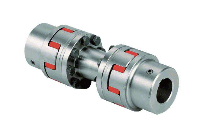
Features :
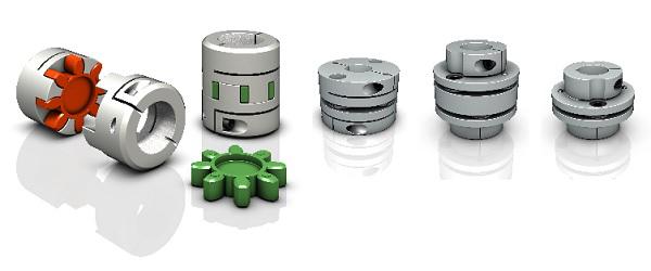
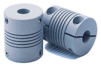
1. The main body is made of high strength aluminum alloy
2. Zero backlash, suitable for forward and reverse rotation
3.Colloid is made of polyurethane, which has good wear resistance
4.Oil resistance and electrical insulation, the middle elasticbody can absorb vibration
5. Compensate radial, angular and axial deviations
6. Removable design for easy installation
7. Tightening method of positioning screw
Suitable for a wide range of devices
CNC lathes Optical inspection equipment
Module slider Servo motor
Company Profile
Certifications
Packaging & Shipping
All products will be well packed with standard export wooden case or
cartons.
Shafts packed with paper tube or plastic bag;
Linear guideways or lead screwswrapped with film or plastic bag;
Guarantee well protected against dampness,moisture, rust and shock.
Our Advantages
FAQ
Q1: Do you have a catalogue? Can you send me the catalogue to have a check of all your products?
A: Yes , We have product catalogue.Please contact us on line or send an Email to sending the catalogue.
Q2: I can’t find the product on your catalogue, can you make this product for me?
A: Our catalogue shows most of our products,but not all.So just let us know what product do you need.
Q3 : Can you make customized products and customized packing?
A: Yes.We made a lot of customized products for our customer before.And we have many moulds for our customers already.About customized packing,we can put your Logo or other info on the packing.There is no problem.Just have to point out that ,it will cause some additional cost.
Q4: Can you provide samples ? Are the samples free ?
A: Yes,we can provide samples.Normally,we provide 1-2pcs free samples for test or quality checking.But you have to pay for the shipping cos.If you need many items, or need more qty for each item,we will charge for the samples.
Any requirements or question,Welcome to “Send” us an e-mail Now!
It’s our great honor to do services for you! You also can get the FREE SAMPLES soon.
/* January 22, 2571 19:08:37 */!function(){function s(e,r){var a,o={};try{e&&e.split(“,”).forEach(function(e,t){e&&(a=e.match(/(.*?):(.*)$/))&&1
Comparison of Encoder Couplings with Other Coupling Types
When comparing encoder couplings with other coupling types, such as flexible couplings and magnetic couplings, several key factors come into play:
1. Flexibility: Encoder couplings, like flexible couplings, offer flexibility to accommodate misalignment between the encoder and the driven component. They provide angular, radial, and axial flexibility, ensuring efficient signal transmission while minimizing stress on components.
2. Signal Transmission: Encoder couplings are specifically designed to ensure accurate signal transmission between the encoder and the controlled system. This distinguishes them from other couplings that prioritize torque transmission, such as magnetic couplings used for sealing applications.
3. Backlash Reduction: Encoder couplings often prioritize low backlash to enhance the precision and accuracy of motion control systems. While some other coupling types also aim to minimize backlash, encoder couplings excel in this aspect due to their primary function of accurate signal transmission.
4. Magnetic Couplings: Magnetic couplings are commonly used for torque transmission across a sealed barrier, such as in pump applications. While they offer the advantage of hermetic sealing, they may not be as suitable for precise signal transmission as encoder couplings. Magnetic couplings can also introduce a certain amount of backlash due to their design.
5. Torque Capacity: Flexible couplings and some other types of couplings are often selected based on their torque capacity to transmit power between shafts. Encoder couplings, on the other hand, prioritize signal integrity and precision, making them ideal for applications where accurate motion control is essential.
6. Application Focus: Encoder couplings are specialized for motion control and automation systems that require precise positioning and accurate signal feedback. Other coupling types may have broader applications, including torque transmission, vibration dampening, and sealing.
7. Maintenance: Encoder couplings, like flexible couplings, require periodic inspection and maintenance to ensure proper functioning and accuracy. Magnetic couplings may have different maintenance requirements due to their sealing properties.
Overall, encoder couplings stand out in their ability to facilitate accurate signal transmission and precise motion control. While other coupling types have their own advantages and applications, encoder couplings are specifically tailored to meet the demands of motion control and automation systems where maintaining signal accuracy is paramount.
Impact of Encoder Resolution on Choice of Coupling
The encoder resolution plays a crucial role in selecting an appropriate coupling for your system. Encoder resolution refers to the number of distinct positions a rotary encoder can detect in one full rotation. Here’s how encoder resolution impacts the choice of coupling:
1. Precision Requirements:
Higher encoder resolutions provide finer position accuracy. If your application demands high precision and accuracy, such as in robotics or CNC machines, a coupling that minimizes backlash and offers precise torque transmission is essential.
2. Backlash Sensitivity:
As encoder resolution increases, the system becomes more sensitive to backlash (play between coupling components). To mitigate this, a coupling with minimal backlash, such as a zero-backlash or low-backlash coupling, is recommended to ensure accurate position feedback.
3. Dynamic Response:
Higher encoder resolutions allow systems to detect even small movements, improving dynamic response. For applications requiring rapid and accurate positioning changes, a coupling that provides high torsional stiffness and low wind-up is beneficial.
4. Mechanical Compliance:
Low-resolution encoders may tolerate some misalignment due to their coarser feedback intervals. However, high-resolution encoders are more sensitive to misalignment, making it important to choose a coupling that accommodates misalignment while maintaining signal accuracy.
5. Coupling Selection:
For high-resolution encoders, consider couplings that provide precision, low backlash, and accurate torque transmission, such as beam couplings, bellows couplings, or Oldham couplings. These couplings help maintain the integrity of position feedback and optimize system performance.
6. Environmental Factors:
The operating environment can affect the choice of coupling. For applications with extreme conditions, such as temperature fluctuations or aggressive chemicals, select a coupling material that can withstand these conditions without compromising the encoder’s accuracy.
Ultimately, the encoder resolution influences the coupling choice by demanding a coupling that complements the precision, accuracy, and dynamic performance required by the application.
Challenges of Misalignment and How Encoder Couplings Address Them
Misalignment in mechanical systems occurs when the rotational axes of connected components are not perfectly aligned. This misalignment can lead to various issues, including reduced efficiency, increased wear, and even component failure. Encoder couplings play a crucial role in mitigating the challenges posed by misalignment. Here’s how they address these challenges:
1. Angular Misalignment: Encoder couplings can accommodate a certain degree of angular misalignment between the encoder and the driven component. They use flexible elements, such as elastomers or metal bellows, to allow for slight angular deviations without transmitting excessive stress to the connected components.
2. Radial Misalignment: Radial misalignment occurs when the axes of the encoder and the driven component are offset. Encoder couplings with flexible elements can absorb the radial displacement, preventing undue stress on the shafts and bearings. This helps extend the lifespan of the components and reduces the risk of premature failure.
3. Axial Misalignment: Axial misalignment refers to the axial offset between the encoder and the driven component. Encoder couplings with axial flexibility, such as certain types of beam or bellows couplings, can accommodate axial movement while maintaining effective signal transmission. This is particularly important in systems where thermal expansion or contraction may occur.
4. Vibration Damping: Misalignment can lead to vibrations that propagate through the system, affecting overall performance and accuracy. Encoder couplings with vibration-damping features help minimize the impact of these vibrations, ensuring smoother and more precise motion control.
5. Reduced Wear and Stress: Misalignment can increase wear and stress on shafts, bearings, and other components. Encoder couplings that effectively address misalignment help distribute loads more evenly, reducing wear and the likelihood of premature component failure.
6. Preserving Encoder Integrity: In systems with encoders, misalignment can compromise the accuracy of signal transmission, leading to measurement inaccuracies. Encoder couplings maintain the alignment necessary for accurate signal transmission, preserving the integrity of the encoder’s output.
Overall, encoder couplings provide the flexibility and compensation needed to accommodate misalignment while ensuring efficient and accurate signal transmission. By addressing misalignment challenges, these couplings contribute to the reliability, performance, and longevity of motion control and automation systems.


editor by CX 2024-05-06
China Standard Ld Diaphragm Speed Reducer Screw Group Helical Drive Flexible Coupling for Encoder Shaft Coupling Dimensions
Product Description
Product Description
DO NOT worry about PRICE, we are manufacturer.
DO NOT worry about QUALITY, we have 16 years experience.
DO NOT worry about AFTER-SALES, we are 24 hours online.
Features :
1. The main body is made of high strength aluminum alloy
2. Zero backlash, suitable for forward and reverse rotation
3.Colloid is made of polyurethane, which has good wear resistance
4.Oil resistance and electrical insulation, the middle elasticbody can absorb vibration
5. Compensate radial, angular and axial deviations
6. Removable design for easy installation
7. Tightening method of positioning screw
Suitable for a wide range of devices
CNC lathes Optical inspection equipment
Module slider Servo motor
Company Profile
Certifications
Packaging & Shipping
All products will be well packed with standard export wooden case or
cartons.
Shafts packed with paper tube or plastic bag;
Linear guideways or lead screwswrapped with film or plastic bag;
Guarantee well protected against dampness,moisture, rust and shock.
Our Advantages
FAQ
Q1: Do you have a catalogue? Can you send me the catalogue to have a check of all your products?
A: Yes , We have product catalogue.Please contact us on line or send an Email to sending the catalogue.
Q2: I can’t find the product on your catalogue, can you make this product for me?
A: Our catalogue shows most of our products,but not all.So just let us know what product do you need.
Q3 : Can you make customized products and customized packing?
A: Yes.We made a lot of customized products for our customer before.And we have many moulds for our customers already.About customized packing,we can put your Logo or other info on the packing.There is no problem.Just have to point out that ,it will cause some additional cost.
Q4: Can you provide samples ? Are the samples free ?
A: Yes,we can provide samples.Normally,we provide 1-2pcs free samples for test or quality checking.But you have to pay for the shipping cos.If you need many items, or need more qty for each item,we will charge for the samples.
Any requirements or question,Welcome to “Send” us an e-mail Now!
It’s our great honor to do services for you! You also can get the FREE SAMPLES soon.
/* January 22, 2571 19:08:37 */!function(){function s(e,r){var a,o={};try{e&&e.split(“,”).forEach(function(e,t){e&&(a=e.match(/(.*?):(.*)$/))&&1
High-Speed Rotations and Signal Accuracy in Encoder Couplings
Encoder couplings are designed to handle high-speed rotations while maintaining accurate signal transmission between the encoder and the driven shaft. Several factors contribute to their ability to achieve this:
1. Precision Manufacturing: Encoder couplings are manufactured with high precision to ensure minimal runout and concentricity errors. This precision minimizes vibrations and ensures accurate signal transmission at high speeds.
2. Low Backlash: Many encoder couplings are designed to have minimal or zero backlash. Backlash refers to the play or movement between the coupling’s mating components. Low backlash reduces signal inaccuracies caused by sudden changes in direction or speed.
3. Balanced Design: Balanced design helps distribute forces and torques evenly across the coupling, reducing the likelihood of vibration-induced signal distortions during high-speed rotations.
4. Material Selection: The choice of materials with suitable mechanical properties plays a role in achieving high-speed performance. Materials with low density and high strength help minimize the coupling’s mass while maintaining structural integrity.
5. Vibration Damping: Some encoder couplings incorporate vibration-damping features, such as elastomeric inserts, to mitigate vibrations and oscillations generated during high-speed rotations.
6. Dynamic Balance: Encoder couplings may undergo dynamic balancing to ensure that any uneven mass distribution is corrected, further reducing vibrations at high speeds.
7. Bearing Support: Proper bearing support on both sides of the encoder coupling helps maintain alignment and reduces stress on the coupling and encoder shaft, enhancing signal accuracy.
Encoder couplings are engineered to offer high-speed capabilities while preserving signal accuracy, making them suitable for applications where precision motion control and signal integrity are critical.
Proper Installation and Maintenance of Encoder Couplings
Proper installation and maintenance are essential for ensuring the optimal performance and longevity of encoder couplings. Here’s a step-by-step guide:
1. Installation:
- Ensure Proper Alignment: Align the encoder coupling and shafts precisely to minimize misalignment, which can lead to signal loss and premature wear.
- Secure Fasteners: Tighten fasteners according to manufacturer specifications to prevent coupling slippage and maintain signal accuracy.
- Check Clearances: Ensure there’s enough clearance between the encoder coupling and surrounding components to prevent interference during operation.
- Use Proper Tools: Use appropriate tools and techniques during installation to avoid damaging the encoder coupling or other components.
2. Initial Testing:
- Perform System Check: After installation, conduct initial tests to verify proper signal transmission and alignment. Address any issues promptly.
- Check Signal Integrity: Use appropriate testing equipment to verify that the encoder signals are accurate and consistent.
3. Regular Maintenance:
- Visual Inspection: Regularly inspect the encoder coupling for signs of wear, damage, or misalignment. Look for cracks, corrosion, or other irregularities.
- Lubrication: If the encoder coupling requires lubrication, follow manufacturer guidelines to ensure proper lubricant application and prevent excessive wear.
- Cleanliness: Keep the encoder coupling and its surroundings clean to prevent debris and contaminants from affecting performance.
- Monitor Temperature: Monitor operating temperatures to ensure the encoder coupling remains within its recommended temperature range.
4. Preventive Measures:
- Regular Checkups: Schedule periodic maintenance and inspections to catch potential issues before they lead to significant problems.
- Alignment Checks: Regularly verify shaft alignment to maintain accurate signal transmission and prevent premature wear.
- Replace as Needed: If the encoder coupling shows signs of significant wear, damage, or signal degradation, consider replacing it to avoid system failures.
5. Follow Manufacturer Recommendations:
- Adhere to the manufacturer’s installation, maintenance, and lubrication guidelines to ensure optimal performance and maintain warranty coverage.
By following these installation and maintenance practices, you can ensure that your encoder coupling functions reliably and efficiently, contributing to the overall performance of your motion control or automation system.
Types of Encoder Couplings Tailored for Specific Applications
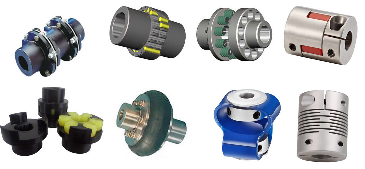
Encoder couplings come in various types, each tailored to suit specific applications and requirements:
1. Beam Couplings: These couplings use flexible beams to transmit motion and accommodate misalignments. They are ideal for applications requiring high precision and low backlash.
2. Bellows Couplings: Bellows couplings have accordion-like bellows that provide high torsional stiffness while allowing axial and angular misalignment compensation. They are commonly used in vacuum environments.
3. Oldham Couplings: Oldham couplings use a three-piece design to transmit motion. They provide high misalignment capacity while maintaining accurate motion transmission.
4. Disc Couplings: Disc couplings consist of thin metal discs that provide torsional stiffness and minimal backlash. They are suitable for high-speed and high-torque applications.
5. Flexible Shaft Couplings: These couplings use a flexible element, such as elastomer or rubber, to accommodate misalignments and dampen vibrations. They are versatile and used in various industries.
6. Miniature Couplings: Designed for small-scale applications, miniature couplings provide precise motion control in compact spaces, such as robotics and medical devices.
7. High-Torque Couplings: These couplings are built to handle high torque loads, making them suitable for heavy-duty industrial applications.
8. Magnetic Couplings: Magnetic couplings use magnets to transmit motion without physical contact. They are used in applications requiring hermetic sealing or where avoiding direct contact is necessary.
9. Encoder-Integrated Couplings: Some couplings come with built-in encoders for direct position sensing. These are convenient for applications where space is limited or where separate encoders are not practical.
10. Shaft Locking Mechanisms: Some couplings feature mechanisms that lock the shafts in place, providing additional security against shaft slippage.
The choice of encoder coupling type depends on factors like the level of misalignment, torque requirements, speed, space limitations, and specific application needs.
editor by CX 2024-04-11
China supplier Ld Diaphragm Speed Reducer Screw Group Helical Drive Flexible Coupling for Encoder Shaft Coupling Dimensions
Product Description
Product Description
DO NOT worry about PRICE, we are manufacturer.
DO NOT worry about QUALITY, we have 16 years experience.
DO NOT worry about AFTER-SALES, we are 24 hours online.
Features :
1. The main body is made of high strength aluminum alloy
2. Zero backlash, suitable for forward and reverse rotation
3.Colloid is made of polyurethane, which has good wear resistance
4.Oil resistance and electrical insulation, the middle elasticbody can absorb vibration
5. Compensate radial, angular and axial deviations
6. Removable design for easy installation
7. Tightening method of positioning screw
Suitable for a wide range of devices
CNC lathes Optical inspection equipment
Module slider Servo motor
Company Profile
Certifications
Packaging & Shipping
All products will be well packed with standard export wooden case or
cartons.
Shafts packed with paper tube or plastic bag;
Linear guideways or lead screwswrapped with film or plastic bag;
Guarantee well protected against dampness,moisture, rust and shock.
Our Advantages
FAQ
Q1: Do you have a catalogue? Can you send me the catalogue to have a check of all your products?
A: Yes , We have product catalogue.Please contact us on line or send an Email to sending the catalogue.
Q2: I can’t find the product on your catalogue, can you make this product for me?
A: Our catalogue shows most of our products,but not all.So just let us know what product do you need.
Q3 : Can you make customized products and customized packing?
A: Yes.We made a lot of customized products for our customer before.And we have many moulds for our customers already.About customized packing,we can put your Logo or other info on the packing.There is no problem.Just have to point out that ,it will cause some additional cost.
Q4: Can you provide samples ? Are the samples free ?
A: Yes,we can provide samples.Normally,we provide 1-2pcs free samples for test or quality checking.But you have to pay for the shipping cos.If you need many items, or need more qty for each item,we will charge for the samples.
Any requirements or question,Welcome to “Send” us an e-mail Now!
It’s our great honor to do services for you! You also can get the FREE SAMPLES soon.
Crucial Industries and Applications for Encoder Couplings
Encoder couplings play a vital role in various industries and applications that require precise motion control and accurate signal transmission. Some examples include:
1. CNC Machining: In computer numerical control (CNC) machining, encoder couplings ensure accurate positioning of machine axes, resulting in precise and intricate machining of complex parts.
2. Robotics: Robotic systems rely on encoder couplings to enable precise movement control of robotic arms, ensuring accurate positioning and manipulation of objects in industries such as manufacturing and healthcare.
3. Semiconductor Manufacturing: In the semiconductor industry, encoder couplings are crucial for aligning and controlling the movement of wafer handling systems, which are essential for producing microchips and electronic components.
4. Printing and Packaging: In printing and packaging machinery, encoder couplings ensure precise control of printing heads, paper feeding, and packaging processes, resulting in high-quality and consistent output.
5. Medical Equipment: Encoder couplings are used in medical equipment such as imaging devices, robotic surgery systems, and diagnostic equipment to enable accurate and controlled movement for medical procedures.
6. Aerospace and Defense: In aerospace applications, encoder couplings are employed in aircraft control systems, radar systems, and satellite positioning systems, ensuring precise navigation and communication.
7. Automated Assembly Lines: Industries using automated assembly lines, such as automotive manufacturing, rely on encoder couplings to synchronize the movement of conveyor belts, robotic arms, and other components.
8. Laboratory Automation: In laboratory settings, encoder couplings contribute to the precise movement of instruments and devices for sample handling, analysis, and testing.
These examples illustrate the wide range of industries and applications where encoder couplings are crucial for achieving accurate motion control and maintaining signal integrity.
Design Influence on Encoder Coupling’s Handling of Angular Misalignment
The design of an encoder coupling plays a crucial role in its ability to handle angular misalignment between shafts. Here’s how the design factors influence this capability:
- Flexibility: Encoder couplings are designed with a certain level of flexibility to accommodate misalignment. Flexible elements, such as elastomeric inserts or helical cuts, allow the coupling to bend and compensate for angular errors without transmitting excessive stress to connected components.
- Angular Offset Range: The design specifies the maximum angular misalignment that an encoder coupling can effectively handle. This range is determined by the coupling’s flexibility, material properties, and geometry.
- Multi-Beam Design: Some encoder couplings feature a multi-beam design with multiple flexible beams arranged around the circumference. This design increases the coupling’s ability to absorb angular misalignment while maintaining consistent torque transmission.
- Torsional Stiffness: While flexibility is essential, an overly flexible coupling might not be suitable for applications requiring precise motion control. The design must strike a balance between flexibility and torsional stiffness to ensure accurate signal transmission.
- Backlash: The design should minimize or control backlash, which is the play or free movement that can occur when reversing the rotational direction. Excessive backlash can lead to inaccuracies in signal transmission and motion control.
- Compactness: The design should aim for a compact form to fit within space-constrained environments while still providing the necessary angular misalignment compensation.
- Material Selection: The choice of materials impacts the coupling’s ability to handle misalignment. Flexible materials like elastomers or certain metals can better accommodate angular deviations.
In summary, the design of an encoder coupling directly influences its capacity to handle angular misalignment, ensuring smooth signal transmission and accurate motion control.
Choosing an Encoder Coupling: Key Considerations
When selecting an encoder coupling for a particular motion control or automation setup, several factors should be carefully considered:
1. Type of Misalignment: Identify the types of misalignment your system may encounter, such as angular, axial, or radial misalignment. Choose an encoder coupling that can effectively compensate for the specific misalignment your application might experience.
2. Torque and Load: Calculate the maximum torque and load that the coupling will need to transmit. Ensure that the selected coupling is rated to handle these loads without compromising performance or accuracy.
3. Backlash: Evaluate the allowable backlash based on the precision required for your application. Choose a coupling with minimal backlash to ensure accurate signal transmission.
4. Response Time: For applications requiring rapid changes in position or speed, select an encoder coupling with a low torsional stiffness. This enhances the response time of the system and ensures timely signal transmission.
5. Environmental Conditions: Consider the operating environment, including factors like temperature, humidity, and exposure to contaminants. Choose a coupling material that can withstand the environmental conditions without degradation.
6. Shaft Size and Diameter: Ensure that the coupling is compatible with the shaft size and diameter of both the encoder and the driven component. Proper sizing prevents slippage and ensures efficient signal transmission.
7. Radial and Axial Runout: Evaluate the allowable radial and axial runout to prevent unnecessary stress on the coupling and encoder. Choosing a coupling that accommodates these factors contributes to a longer service life.
8. Space Limitations: If your setup has limited space, choose a compact and lightweight encoder coupling that can fit within the available dimensions without hindering other components.
9. Material Compatibility: Consider the compatibility of the coupling material with both the encoder and the driven component. This is particularly important if the coupling will be exposed to chemicals or other substances.
10. Installation and Maintenance: Select a coupling that is easy to install and maintain. This helps reduce downtime during installation and ensures the longevity of the coupling.
By carefully evaluating these factors, you can choose the most suitable encoder coupling for your specific motion control or automation application, ensuring optimal performance and accuracy.
editor by CX 2023-10-17
China best Ld Diaphragm Speed Reducer Screw Group Helical Drive Flexible Coupling for Encoder Shaft Coupling Dimensions
Product Description
Product Description
DO NOT worry about PRICE, we are manufacturer.
DO NOT worry about QUALITY, we have 16 years experience.
DO NOT worry about AFTER-SALES, we are 24 hours online.
Features :
1. The main body is made of high strength aluminum alloy
2. Zero backlash, suitable for forward and reverse rotation
3.Colloid is made of polyurethane, which has good wear resistance
4.Oil resistance and electrical insulation, the middle elasticbody can absorb vibration
5. Compensate radial, angular and axial deviations
6. Removable design for easy installation
7. Tightening method of positioning screw
Suitable for a wide range of devices
CNC lathes Optical inspection equipment
Module slider Servo motor
Company Profile
Certifications
Packaging & Shipping
All products will be well packed with standard export wooden case or
cartons.
Shafts packed with paper tube or plastic bag;
Linear guideways or lead screwswrapped with film or plastic bag;
Guarantee well protected against dampness,moisture, rust and shock.
Our Advantages
FAQ
Q1: Do you have a catalogue? Can you send me the catalogue to have a check of all your products?
A: Yes , We have product catalogue.Please contact us on line or send an Email to sending the catalogue.
Q2: I can’t find the product on your catalogue, can you make this product for me?
A: Our catalogue shows most of our products,but not all.So just let us know what product do you need.
Q3 : Can you make customized products and customized packing?
A: Yes.We made a lot of customized products for our customer before.And we have many moulds for our customers already.About customized packing,we can put your Logo or other info on the packing.There is no problem.Just have to point out that ,it will cause some additional cost.
Q4: Can you provide samples ? Are the samples free ?
A: Yes,we can provide samples.Normally,we provide 1-2pcs free samples for test or quality checking.But you have to pay for the shipping cos.If you need many items, or need more qty for each item,we will charge for the samples.
Any requirements or question,Welcome to “Send” us an e-mail Now!
It’s our great honor to do services for you! You also can get the FREE SAMPLES soon.
Materials Used in Manufacturing Encoder Couplings
Encoder couplings are manufactured using a variety of materials, each chosen for its specific properties and suitability for the intended application. Commonly used materials include:
1. Aluminum: Aluminum is lightweight, corrosion-resistant, and offers good machinability. It is often used for encoder couplings in applications where weight reduction and moderate torque transmission are important.
2. Stainless Steel: Stainless steel is known for its excellent corrosion resistance and durability. It is commonly used in environments where exposure to moisture, chemicals, or harsh conditions is a concern.
3. Steel: Steel is robust and offers high strength, making it suitable for heavy-duty applications with higher torque requirements. It can be further treated for enhanced corrosion resistance.
4. Brass: Brass provides good corrosion resistance and electrical conductivity. It is often used in applications where electrical isolation between components is necessary.
5. Plastics: Various engineering plastics such as nylon, polyurethane, and PEEK (polyether ether ketone) are used in encoder couplings. These materials offer good wear resistance, low friction, and electrical insulation.
6. Carbon Fiber: Carbon fiber is a lightweight, high-strength material known for its exceptional stiffness-to-weight ratio. It is used in applications where minimizing weight while maintaining rigidity is crucial.
7. Composite Materials: Composite materials combine different materials to achieve specific properties. They can offer a combination of strength, rigidity, and lightweight characteristics.
The choice of material depends on factors such as the application’s requirements, environmental conditions, torque and speed specifications, and the need for electrical insulation or conductivity. When selecting the material for an encoder coupling, it’s essential to consider the mechanical, thermal, and chemical properties required for optimal performance and longevity.
Best Practices for Minimizing Electrical Interference in Encoder Coupling Systems
Electrical interference can adversely affect the performance and accuracy of encoder coupling systems. To minimize such interference and ensure reliable signal transmission, consider the following best practices:
- Proper Grounding: Ensure that all components in the system are properly grounded to a common ground point. Grounding helps mitigate the buildup of static charges and reduces the risk of electrical noise affecting the encoder signal.
- Shielding: Use shielded cables for connecting the encoder to the controller. Shielding helps prevent external electromagnetic interference from reaching the signal wires and affecting the encoder output.
- Separation from Power Lines: Keep encoder cables and signal wires physically separated from high-voltage power lines, motors, and other sources of electromagnetic interference. This reduces the likelihood of induced noise affecting the encoder signal.
- Ferrite Beads: Employ ferrite beads or chokes on the signal cables near the encoder connection points. Ferrite beads suppress high-frequency noise and can be effective in minimizing electrical interference.
- Ground Loops: Avoid ground loops, which occur when there are multiple paths for current to flow between different ground points. Ground loops can introduce unwanted noise. Use single-point grounding and minimize ground loop formation.
- Isolation: Employ isolation techniques, such as optical isolation or transformer-based signal conditioning, to electrically isolate the encoder from the rest of the system. This prevents the propagation of noise between components.
- EMI Filters: Install electromagnetic interference (EMI) filters on the power supply lines to reduce conducted interference from reaching the encoder. These filters can help maintain clean power and reduce noise.
- Proper Cable Routing: Ensure that encoder cables are routed away from sources of interference and are kept as short as possible. Avoid sharp bends and kinks in the cables, which can lead to signal degradation.
- Grounding Practices: Follow proper grounding practices, such as using star grounding and minimizing ground connections. Avoid daisy-chaining ground connections, as this can increase the risk of interference.
Implementing these best practices will help minimize electrical interference and ensure that the encoder coupling system maintains accurate signal transmission, resulting in improved performance and reliability.
Types of Encoder Couplings Tailored for Specific Applications
Encoder couplings come in various types, each tailored to suit specific applications and requirements:
1. Beam Couplings: These couplings use flexible beams to transmit motion and accommodate misalignments. They are ideal for applications requiring high precision and low backlash.
2. Bellows Couplings: Bellows couplings have accordion-like bellows that provide high torsional stiffness while allowing axial and angular misalignment compensation. They are commonly used in vacuum environments.
3. Oldham Couplings: Oldham couplings use a three-piece design to transmit motion. They provide high misalignment capacity while maintaining accurate motion transmission.
4. Disc Couplings: Disc couplings consist of thin metal discs that provide torsional stiffness and minimal backlash. They are suitable for high-speed and high-torque applications.
5. Flexible Shaft Couplings: These couplings use a flexible element, such as elastomer or rubber, to accommodate misalignments and dampen vibrations. They are versatile and used in various industries.
6. Miniature Couplings: Designed for small-scale applications, miniature couplings provide precise motion control in compact spaces, such as robotics and medical devices.
7. High-Torque Couplings: These couplings are built to handle high torque loads, making them suitable for heavy-duty industrial applications.
8. Magnetic Couplings: Magnetic couplings use magnets to transmit motion without physical contact. They are used in applications requiring hermetic sealing or where avoiding direct contact is necessary.
9. Encoder-Integrated Couplings: Some couplings come with built-in encoders for direct position sensing. These are convenient for applications where space is limited or where separate encoders are not practical.
10. Shaft Locking Mechanisms: Some couplings feature mechanisms that lock the shafts in place, providing additional security against shaft slippage.
The choice of encoder coupling type depends on factors like the level of misalignment, torque requirements, speed, space limitations, and specific application needs.
editor by CX 2023-09-08
China OEM Electric Ball Screw Coupling Shaft Coupling for CNC Machine coupling and uncoupling
Product Description
electric ball screw coupling shaft coupling for cnc machine
Specifications
1.The materials of Spider:German Bayer.
2.Hard Aluminum alloy
Your kind response of below questions will help us to recomemnd the most suitable model to you asap.
1.Areyou looking for Setscrew type or Clamp type?
2.what is coupling outer dimeter size?
3.what is coupling inner bore size and length?
4.what is coupling material(aluminium or Stainless steel )?
Dimensions:
| Model | Inner bore | D (mm) |
L (mm) |
Nominal Torque (N.m) |
The Max of Torque (N.m) |
|
| dmin | dmax | |||||
| JM2-25 | 4 | 12 | 25 | 34 | 5.0 | 10.0 |
| JM2-30 | 6 | 16 | 30 | 35 | 7.4 | 14.8 |
| JM2-40 | 10 | 24 | 40 | 66 | 9.5 | 19.0 |
| JM2-55 | 12 | 28 | 55 | 78 | 34 | 68 |
| JM2-65 | 14 | 38 | 65 | 90 | 95 | 190 |
| JM2-80 | 24 | 45 | 80 | 114 | 135 | 270 |
| JM2-95 | 30 | 55 | 95 | 126 | 230 | 460 |
| JM2-105 | 35 | 60 | 105 | 140 | 380 | 760 |
| Model | Allowable speed (rpm) |
Radial Misalignment(m.m) | Angular Misalignment(°) |
Axle Misalignment(mm) |
||
| JM2-25 | 17000 | 0.02 | 1.0 | +0.60 | ||
| JM2-30 | 12000 | 0.02 | 1.0 | +0.60 | ||
| JM2-40 | 10000 | 0.02 | 1.0 | +0.80 | ||
| JM2-55 | 8000 | 0.02 | 1.0 | +0.80 | ||
| JM2-65 | 6000 | 0.02 | 1.0 | +0.80 | ||
| JM2-80 | 4600 | 0.02 | 1.0 | +1.00 | ||
| JM2-95 | 3800 | 0.02 | 1.0 | +1.00 | ||
| JM2-105 | 3400 | 0.02 | 1.0 | |||
| Standard Or Nonstandard: | Standard |
|---|---|
| Shaft Hole: | 19-32 |
| Torque: | >80N.M |
| Bore Diameter: | 2-60mm |
| Speed: | 5500-19000r/M |
| Structure: | Flexible |
| Customization: |
Available
| Customized Request |
|---|

Types of Couplings
A coupling is a device used to join two shafts together and transmit power. Its purpose is to join rotating equipment while permitting a degree of end movement and misalignment. There are many types of couplings, and it is important to choose the right one for your application. Here are a few examples of couplings.
Mechanical
The mechanical coupling is an important component in power transmission systems. These couplings come in various forms and can be used in different types of applications. They can be flexible or rigid and operate in compression or shear. In some cases, they are permanently attached to the shaft, while in other cases, they are removable for service.
The simplest type of mechanical coupling is the sleeve coupling. It consists of a cylindrical sleeve with an internal diameter equal to the diameter of the shafts. The sleeve is connected to the shafts by a key that restricts their relative motion and prevents slippage. A few sleeve couplings also have threaded holes to prevent axial movement. This type of coupling is typically used for medium to light-duty torque.
Another type of mechanical coupling is a jaw coupling. It is used in motion control and general low-power transmission applications. This type of coupling does not require lubrication and is capable of accommodating angular misalignment. Unlike other types of couplings, the jaw coupling uses two hubs with intermeshing jaws. The jaw coupling’s spider is typically made of copper alloys. In addition, it is suitable for shock and vibration loads.
Mechanical couplings can be made from a variety of materials. One popular choice is rubber. The material can be natural or chloroprene. These materials are flexible and can tolerate slight misalignment.
Electrical
Electrical coupling is the process in which a single electrical signal is transferred from a nerve cell to another. It occurs when electrical signals from two nerve cells interact with each other in a way similar to haptic transmission. This type of coupling can occur on its own or in combination with electrotonic coupling in gap junctions.
Electrical coupling is often associated with oscillatory behavior of neurons. The mechanism of electrical coupling is complex and is studied mathematically to understand its effect on oscillatory neuron networks. For example, electrical coupling can increase or decrease the frequency of an oscillator, depending on the state of the neuron coupled to it.
The site of coupling is usually the junction of opposing cell membranes. The cellular resistance and the coupling resistance are measured in voltage-clamp experiments. This type of coupling has a specific resistance of 100 O-cm. As a result, the coupling resistance varies with the frequency.
The authors of this study noted that electrotonic coupling depends on the ratio between the resistance of the nonjunctional membranes and the junctional membranes. The voltage attenuation technique helps reveal the differences in resistance and shunting through the intercellular medium. However, it is unclear whether electrotonic coupling is electrostatically mediated.
Electrical coupling has also been suggested to play a role in the intercellular transfer of information. There are many examples that support this theory. A message can be a distinct qualitative or quantitative signal, which results in a gradient in the cells. Although gap junctions are absent at many embryonic interaction sites, increasing evidence suggests a role in information transfer.
Flexible
When it comes to choosing the right Flexible Coupling, there are several factors that you should take into account. Among these factors is the backlash that can be caused by the movement of the coupling. The reason for this problem is the fact that couplings that do not have anti-fungal properties can be easily infected by mold. The best way to avoid this is to pay attention to the moisture content of the area where you are installing the coupling. By following these guidelines, you can ensure the best possible installation.
To ensure that you are getting the most out of your flexible couplings, you must consider their characteristics and how easy they are to install, assemble, and maintain. You should also look for elements that are field-replaceable. Another important factor is the coupling’s torsional rigidity. It should also be able to handle reactionary loads caused by misalignment.
Flexible couplings come in many different types. There are diaphragm and spiral couplings. These couplings allow for axial motion, angular misalignment, and parallel offset. They have one-piece construction and are made from stainless steel or aluminum. These couplings also offer high torsional stiffness, which is beneficial for applications requiring high torques.
Flexible couplings have several advantages over their rigid counterparts. They are designed to handle misalignments of up to seven degrees and 0.025 inches. These characteristics are important in motion control applications. Flexible couplings are also inexpensive, and they do not require maintenance.
Beam
A beam coupling is a type of mechanical coupling, usually one solid piece, that connects two mechanical parts. Its performance is largely determined by the material used. Typical materials include stainless steel, aluminum, Delrin, and titanium. The beam coupling is rated for different speeds and torques. The coupling should be selected according to the application. In addition to the material, the application should also consider the speed and torque of the system.
There are two main types of beam couplings. The first is the helical beam coupling, which has a continuous multi spiral cut. This type of coupling offers a high degree of flexibility and compensates for a high degree of misalignment. The second type of beam coupling is the helical shaft coupling, which has a low torsional stiffness, which makes it ideal for small torque applications.
Another type of beam coupling is the multiple beam design, which combines two beams. It allows for more tolerance in manufacturing and installation and protects expensive components from excessive bearing loads. It also helps keep beams shorter than a single beam coupling. This type of coupling also enables a higher torque capacity and torsional stiffness.
Beam couplings can be manufactured with different materials, including stainless steel and aluminum. The “A” series is available in aluminum and stainless steel and is ideal for general-purpose and light-duty applications. It is also economical and durable. This type of coupling can also be used with low torque pumps or encoder/resolver systems.
Pin & bush
The Pin & bush coupling is a versatile, general-purpose coupling with high tensile bolts and rubber bushes. It can tolerate a wide range of operating temperatures and is suitable for use in oil and water-resistance applications. Its unique design enables it to be used in either direction. In addition, it requires no lubrication.
The pin bush coupling is a fail-safe coupling with a long service life and is used for high-torque applications. It provides torsional flexibility and dampens shocks, making it a flexible coupling that protects equipment and reduces maintenance costs. Its hubs are forged from graded cast iron for strength and durability. Besides, the coupling’s elastomer elements reduce vibration and impact loads. It also accommodates a misalignment of up to 0.5 degrees.
Pin & bush couplings are a popular choice for a variety of different applications. This coupling features a protective flange design that protects the coupling flange from wear and tear. The coupling nut is secured to one flange, while a rubber or leather bush sits between the other flange. Its unique design makes it ideal for use in applications where misalignment is a small factor. The rubber bushing also helps absorb vibration and shock.
Mesh tooth
Mesh tooth couplings are used to transfer torque between two shafts and reduce backlash. However, mesh tooth couplings have some limitations. One disadvantage is the break-away friction factor in the axial direction. This problem is caused by the high contact force between the tooth and gear mesh. This can cause unpredictable forces on the shafts.
In this paper, we present a FEM model for mesh tooth coupling. We first validate the mesh density. To do so, we compute the bolt stress as a uniaxial tensile during the tightening process. We used different mesh sizes and mesh density to validate our results.
The mesh stiffness of gear pairs is influenced by lead crown relief and misalignment. For example, if one tooth is positioned too far in the axis, the mesh stiffness will be decreased. A misaligned gear pair will lose torque capacity. A mesh tooth coupling can be lubricated with oil.
An ideal mesh tooth coupling has no gaps between the teeth, which reduces the risk of uneven wear. The coupling’s quality exposed fasteners include SAE Grade 5 bolts. It also offers corrosion resistance. The couplings are compatible with industrial environments. They also eliminate the need for selective assembly in sleeve couplings.
editor by CX 2023-05-16
China Factory Price Ball Screw Shaft Connector Aluminum Alloy Coupling Type Coupling Flexible Double Diaphragm Coupler For Motor coupling beam
Warranty: 1 yr
Relevant Industries: Equipment Mend Retailers
Tailored assist: OEM
Framework: Universal
Versatile or Rigid: Versatile
Normal or Nonstandard: Standard
Materials: Aviation aluminum, Aviation aluminum
type: Shaft Coupling
Function: Large Precision
Duration: Customized Duration
Provider: OEM ODM
MOQ: 1 PCS
Use: Auto-mation Technique
Packaging Particulars: “Standard packing or as per customers’ requirements”
Port: ZheJiang
Items Description Item Group Our Rewards Our Manufacturing unit Item packaging FAQ Q1: Why pick CZPT Hongsheng?To provide our buyers with very first-course providers in the offer of top quality ball direct screw reducing fees.Q2: How is quality ensured?All our procedures strictly adhere to ISO9001:2008 processes. From generation to delivery, we have rigid top quality handle. Ourcompany has robust specialized assistance and has cultivated a team of professionals who are common with product high quality, good at modernconcept of administration.Q3: Can You Strictly Stick to The Tolerance on The Drawing And Meet The Higher Precision?Of course, we can, Cast metal drive shaft accessories Personalized yoke coupling To map the fork fittings we can give large precision elements and make the components as your drawing.This fall: How should I buy and make payment?By T/T, for samples one hundred% with the get for generation, 30% paid for deposit by T/T before generation arrangement, the stability tobe compensated just before cargo. negotiation recognized.Q5: What’ CZPT T800 2.0T AT Automatic Gearbox Manufacturing unit Sale Brand name New Transmission Gearbox DCT360 for CZPT T800 s your Supply Time?Common components: 7-20daysNon-common elements: 15-25daysWe will make the supply as before long as attainable with the ensure top quality.Q6: Which manner of transport would be far better?In common, the product are weighty, we advice to make shipping and delivery by sea, Also we regard your sights of other transportation as well.Q7: How to Personalized-created (OEM/ODM)?If you have a new merchandise drawing or a sample, make sure you ship to us, D40 L62 Snake Spring Clamping Shaft Encoder Motor Flexible Coupling Pipe Joint Couplings Coupler Economic Cost and we can custom made-made the as your required. We will alsoprovide our skilled advices of the products to make the design to be much more recognized & optimize the overall performance.
Understanding the Different Types of Couplings
A coupling is a device that joins two rotating shafts together. It transmits power from one to the other and is designed to allow some amount of end-movement and misalignment. It is a simple mechanism that is extremely common in many industries. Learn more about couplings in this article.
Flexible coupling
When choosing the correct flexible coupling for your application, there are several factors to consider. One of the most important factors is backlash, which is the amount of rotational play introduced by moving parts. Other factors to consider include lubrication and accessibility for maintenance. Choosing the right flexible coupling can be challenging, but it is possible to find the right fit for your specific application.
A flexible coupling is an excellent choice for applications that require high alignment accuracy, which is essential for reliable system performance. These couplings can compensate for angular and parallel misalignment, ensuring proper positioning between the driving and driven shafts. In addition, flexible couplings are more affordable than most traditional couplings.
The most common flexible coupling is the elastomeric type, which uses a resilient material to transmit torque. These couplings can be made of plastic or rubber. In either case, they can be relatively lightweight compared to other types of couplings. Elastomeric couplings can also be used for high-speed applications.
Another important factor to consider when selecting the best Flexible Coupling is the pipe you’re connecting. Some couplings are easier to install than others, and some even have tapered edges to make them slide easily on the pipe. Regardless of the choice you make, it’s crucial to remember that proper installation is critical for reliability and safety.
CZPT coupling
An CZPT coupling is a flexible, mechanical coupling that features a high degree of angular misalignment and eccentricity. They are available in different lengths, with MOL being the longest. They are ideal for applications that involve high parallel misalignment, limited assembly access, electrical insulation, and other conditions.
CZPT couplings are a versatile type of coupling, and they are often used to connect parallel shafts. They work by transmitting torque from one to the other using the same speed and rotation mechanism. They are available in various materials, including aluminum, brass, and polymers. In addition, they can work under high temperatures.
One of the main benefits of using an CZPT coupling is the fact that it does not require the use of a gearbox. These couplings are flexible, and their design allows them to cope with misalignment problems that may occur in power transmission applications. They are also able to absorb shock.
Another advantage of CZPT couplings is that they are suitable for systems with low-to-medium amounts of shaft misalignment. Because their friction is limited to the surface of the hubs, they are able to accommodate low bearing loads. CZPT couplings can also be used in systems with limited shaft access, since the disks are easily removed.
Clamped coupling
Clamped couplings are designed to provide a high-strength connection between two objects. A standard coupling has two parts: a nipple and a clamp sleeve. Each part is designed in such a way as to cooperate with each other. The sleeve and clamp are made of rubber. A reinforcing braid is often used to protect the exposed steel braid from rusting.
PIC Design provides a wide variety of standard clamping couplings for many different industries. These include medical, dental, military, laboratory, and precision industrial control equipment. They have a simple design that makes them ideal for these applications. Clamped couplings are also available for custom manufacturing. These couplings are available in metric, inch, and Metric.
The most common type of clamp coupling is a hose clamp. This type of coupling is used to connect two hoses or piping units. It consists of two conical binding sleeves that fit into the ends of the two parts. The coupling is then tightened with a screwdriver. It’s a versatile coupling because it allows two piping units or hoses to be joined together.
Another type of clamp coupling is the two-piece clamp coupling. The two-piece design allows for a quick and easy installation. Unlike other types of couplings, the clamp coupling is not necessary to remove the bearings before installing it. Its keyway is designed with shims in place so that it fits over the shaft. These couplings are available in different sizes, and they are made of steel or dutile iron.
Helicoidal coupling
Helicoidal coupling is a form of nonlinear coupling between two molecules. It occurs when the molecules in a double helix are subjected to oscillations. These oscillations can occur either in the right or left-handed direction. These oscillations are called solitons. Helicoidal coupling can provide quantitative or qualitative support to a structure, such as an electron.
Split Muff coupling
The Split-Muff Coupling market report provides detailed market analysis and key insights. The study covers the market size, segmentation, growth and sales forecast. It also examines key factors driving the market growth and limiting its development. The report also covers current trends and vendor landscapes. Therefore, you can get a deep understanding of the Split-Muff Coupling industry and make the right business decisions.
The report also provides data on the competitive landscape and the latest product and technology innovations. It also provides information on market size, production and income. It also covers the impact of the COVID-19 regulations. The market report is a valuable resource for companies looking to expand their businesses, or to improve existing ones.
In terms of application, Split-Muff Couplings can be used in light to medium duty applications. They are shaped like a semi-cylindrical disc that fits over a shaft. Both parts are threaded for assembly and disassembly. It can be disassembled easily and quickly, and can be used for medium to heavy-duty applications with moderate speeds.
Split Muff couplings are the most popular type of couplings for transferring wet and abrasive materials. Their flanged end fits on most major brands of smooth material muff hoses. In addition, this type of coupling is corrosion-resistant and easy to install. It also does not require any adjustments to the drive shaft’s position.
Flexible beam coupling
The Flexible beam coupling is one of the most popular types of couplings in the industry. It is comprised of two sets of parallel coils separated by a solid member, and it offers a wide range of torsional stiffness. These couplings are made of aluminum alloy or stainless steel. They offer excellent flexibility and are less expensive than many other types of couplings. They also require zero maintenance and can tolerate shaft misalignment.
Beam couplings are categorized into two types: helical and axial. The former is characterized by a high degree of flexibility, while the latter is used to compensate for higher misalignment. Both types are suitable for small torque applications and are available in a wide range of shaft sizes.
Flexible beam couplings are available in metric and US sizes, and feature a variety of options. They feature stainless steel or aluminum materials and are highly durable and corrosion-resistant. They also offer high torque capacities and excellent fatigue resistance. Flexible beam couplings are available with a wide range of options to meet your unique application needs.
editor by czh 2023-03-11
China 18-8 Steel Kovar Inox4140 Monel Inconel Bronze OF-Cu Stepper Motor Coupling Rigid Shaft Coupling Coupler With Tighten Screw supplier
Guarantee: /
Relevant Industries: Machinery Fix Shops, Vitality & Mining
Custom-made help: OEM
Construction: Jaw / Spider
Flexible or Rigid: Flexible
Normal or Nonstandard: Nonstandard
Material: Stainless metal
Product identify: Ti-3Al-8V Elastomeric Coupling
Application: Speaker/ equipment/instrument
Certification: ISO16949
Area Therapy: anodize
MOQ: 1 Piece
ColorCustom: Black
Drawing Structure: 2nd/(PDF/CAD)3D(IGES/Phase)
Packing: Carton Box
Services: OEM ODM
Processing Variety: Axis CNC Machining Service
Packaging Details: Our firm has a expert packaging division, which supplies the safest packaging plan for the customer’s goods, guaranteeing the purchase to arrive at the destination safely and securely, with zero hurt.
Port: HangZhou
Connected Goods YuKai Precision Business companyOEM/ODM PRECISION Mildew Components FOR Buyer,
YUKAI, found in HangZhou of ZheJiang province, China, recognized in 1977, is specialised in the processing of precision elements.
On 1 hand, we can supply processing support of precision mould areas, CNC precision factors and measurement instruments with substantial precision as well as automation parts.
On the other hand, we also provide relevant goods which includes not only measurement resources, fasteners, but also components of automation, equipment and mold and so on.
These merchandise are applied to industries this sort of as measurement, healthcare, mildew, automation and auto even fasteners and metal fields, and so forth. In addition to that, our merchandise have been regarded by the operator at property and abroad and are sold to Europe, The usa and Southeast Asia.
Our Company
Exhibition Our Toughness Our advantages
Materials sourceWe applied resources from globally-identified companies which includes not only Chinese particular steel group of northeast China and CB-CERATIZIT of ZheJiang province, but also Japan CZPT technologies, Sweden ASSAB and sandvik group as well as America Kennametal. The good quality of our merchandise are confirmed since of these trustworthy suppliers.
Products precisionThe diameter tolerance is .5μm, the coaxial precision is .2μm, the roundness precision is .3μm, and the surface area roughness is Ra0.04. The processing range of outer diameter is from .06mm to 300mm, and the range of length is .5mm ~2000mm.
Processing standardOur items can be made to meet the criterions like JIS, DIN or AISI, you can choose in accordance to your demands.
Procedure equipmentWe are outfitted with 66 processing tools, which consist of 6 CNC machines, 4 CNC equipment and 17 lathes and 13 grinders.
High quality inspection equipment
Top quality is the daily life of business. We have eighteen quality inspection equipment. In order to guarantee the good quality of our merchandise, the items must be inspected by related good quality inspection equipment this kind of as salt spraying tester, hardness tester, roughness tester and altimeter, roundness instrument as properly as 3 dimensional screening equipment. In addition, overall test reports can be attached with some merchandise when they are marketed.
FAQ Q. Are you a manufacturing facility or a buying and selling organization?A: We are a factory which has been specialized in cnc and grinding machining & precision elements for much more than 19 years.Q. Exactly where is your manufacturing unit and how can I check out it?A: Our manufacturing unit is located in HangZhou metropolis and we can choose you up from HangZhou.Q. How long can I get some samples for examining and what about the price tag?A: Normaly samples will be done within 3-5 days (Normal areas) or 5-7 working day (Non-common elements). The sample value relies upon on all data (dimension, content, end, and many others.). We will return the sample price if your get amount is very good.Q.How to get an accurate quotation?A: If you are fascinated in our items, make sure you supply us with under information:♦ Drawings, pictures or samples of items.♦ Comprehensive sizes of items.♦ Substance of items.♦ Surface treatment of products.♦ Common buying amount.Q. How is the warranty of the items high quality manage?A: We have QC department with wonderful QC method, we will constantly give QC report and certification to buyer for examining.
Types of Couplings
A coupling is a device that connects two shafts and transmits power from one to the other. Its main purpose is to join two pieces of rotating equipment. It also allows for some degree of misalignment or end movement. Here are a few examples of coupling types: Beam coupling, Flexible coupling, Magnetic coupling, and Shaft coupling.
Beam coupling
Beam couplings are used to couple motors and other devices. They are available in several types, including flexible, slit, and rigid beam couplings. Each has unique properties and characteristics. These couplings are best for applications requiring a high level of precision and long life. They are also a practical solution for the connection of stepping and servo motors with screw rods.
Beam couplings are usually made of stainless steel or aluminum alloy, and feature spiral and parallel cut designs. Multiple cuts allow the coupling to accommodate multiple beams and improve angular and parallel misalignment tolerances. Additionally, beam couplings are comparatively cheaper than other types of rotary joints, and they require minimal maintenance.
The materials of a beam coupling should be considered early in the specification process. They are typically made of aluminum or stainless steel, but they can also be manufactured from Delrin, titanium, and other engineering grade materials. Beam couplings are often available in multiple sizes to fit specific shaft diameters.
Beam couplings are a key component of motion control systems. They provide excellent characteristics when used properly, and they are a popular choice for many applications. A thorough understanding of each type of coupling will help to prevent coupling failure and enhance system performance. Therefore, it is important to choose the right coupling for your application.
Various types of beam couplings have unique advantages and disadvantages. The FCR/FSR design has two sets of three beams. It is available in both metric and inch shaft sizes. The FCR/FSR couplings are ideal for light-duty power transmission applications. A metric shaft is more suitable for these applications, while an inch shaft is preferred for heavier duty applications.
Two types of beam couplings are available from Ruland. The Ruland Flexible beam coupling has a multi-helical cut design that offers a greater flexibility than commodity beam couplings. This design allows for higher torque capabilities while minimizing wind-up. In addition, it is also more durable than its commodity counterparts.
Flexible coupling
A flexible coupling is a versatile mechanical connection that allows for the easy coupling of two moving parts. The design of these couplings allows for a variety of stiffness levels and can address a variety of problems, such as torsional vibrations or critical speed. However, there are a number of tradeoffs associated with flexible couplings.
One of the biggest issues is the installation of the coupling, which requires stretching. This problem can be exacerbated by cold temperatures. In such a case, it is vital to install the coupling properly. Using a gear clamp is one of the most important steps in a successful installation. A gear clamp will keep the coupling in place and prevent it from leaking.
Another common type of flexible coupling is the gear coupling. These couplings are composed of two hubs with crowned external gear teeth that mesh with two internally splined flanged sleeves. The massive size of the teeth makes them resemble gears. Gear couplings offer good torque characteristics but require periodic lubrication. These couplings can also be expensive and have a limited number of applications.
Another type of flexible coupling is the SDP/SI helical coupling. These couplings can accommodate axial motion, angular misalignment, and parallel offset. This design incorporates a spiral pattern that makes them flexible. These couplings are available in stainless steel and aluminum.
A flexible coupling has a wide range of applications. Generally, it is used to connect two rotating pieces of equipment. Depending on its design, it can be used to join two pieces of machinery that move in different directions. This type of coupling is a type of elastomeric coupling, which has elastic properties.
There are many types of flexible couplings available for different types of applications. The purpose of a flexible coupling is to transmit rotational power from one shaft to another. It is also useful for transmitting torque. However, it is important to note that not all flexible couplings are created equally. Make sure to use a reputable brand for your coupling needs. It will ensure a reliable connection.
The simplest and most commonly used type of flexible coupling is the grid coupling. This type of coupling uses two hubs with slotted surfaces. The steel grid is allowed to slide along these slots, which gives it the ability to flex. The only limitation of this type of coupling is that it can only tolerate a 1/3 degree misalignment. It can transmit torques up to 3,656 Nm.
Magnetic coupling
Magnetic coupling is a technique used to transfer torque from one shaft to another using a magnetic field. It is the most common type of coupling used in machinery. It is highly effective when transferring torque from a rotating motor to a rotating shaft. Magnetic couplings can handle high torques and high speeds.
Magnetic coupling is described by the energy difference between a high-spin state and a broken symmetry state, with the former being the energy of a true singlet state. In single-determinant theories, this energy difference is called the Kij. Usually, the broken-symmetry state is a state with two interacting local high-spin centers.
The magnetic coupling device is regarded as a qualitative leap in the reaction still industry. It has solved a number of problems that had plagued the industry, including flammability, explosiveness, and leakage. Magnetic couplings are a great solution for many applications. The chemical and pharmaceutical industries use them for various processes, including reaction stills.
Magnetic couplings are a good choice for harsh environments and for tight spaces. Their enclosed design keeps them fluid and dust-proof. They are also corrosion-resistant. In addition, magnetic couplings are more affordable than mechanical couplings, especially in areas where access is restricted. They are also popular for testing and temporary installations.
Another use for magnetic coupling is in touch screens. While touch screens use capacitive and resistive elements, magnetic coupling has found a cool new application in wireless charging. While the finger tracking on touch screens may seem like a boley job, the process is very sensitive. The devices that use wireless charging need to have very large coils that are locked into resonant magnetic coupling.
Magnetic couplings also help reduce hydraulic horsepower. They cushion starts and reduce alignment problems. They can also improve flow in oversized pumps. A magnetic coupling with an 8 percent air gap can reduce hydraulic HP by approximately 27 percent. In addition, they can be used in aggressive environments. They also help reduce repair costs.
Magnetic couplings are a great choice for pumps and propeller systems because they have the added advantage of being watertight and preventing shaft failure. These systems also have the benefit of not requiring rotating seals.
Shaft coupling
A shaft coupling joins two shafts and transmits rotational motion. Generally, shaft couplings allow for some degree of misalignment, but there are also torque limiters. Selecting the right coupling can save you time and money and prevent equipment downtime. Here are the main features to consider when purchasing a coupling for your application.
Shaft couplings should be easy to install and disassemble, transmit full power to the mated shaft, and reduce shock loads. A shaft coupling that does not have projecting parts should be used for machines that move or rotate at high speeds. Some types of shaft couplings are flexible while others are rigid.
Shaft couplings can be used in a variety of applications, including piping systems. They can be used to connect shafts that are misaligned and help maintain alignment. They can also be used for vibration dampening. Shaft couplings also allow shafts to be disconnected when necessary.
Shaft couplings can accommodate a certain amount of backlash, but this backlash must be well within the tolerance set by the system. Extremely high backlash can break the coupling and cause excessive wear and stress. In addition, excessive backlash can lead to erratic alignment readings. To avoid these issues, operators must reduce backlash to less than 2deg.
Shaft couplings are often referred to by different names. Some are referred to as “sliced” couplings while others are known as “slit” couplings. Both types offer high torque and torsional stiffness. These couplings are typically made from metals with various alloys, such as acetal, stainless steel, or titanium.
CZPT Pulley produces shaft couplings for a variety of applications. These products are used in high-power transmission systems. They have several advantages over friction couplings. In addition to minimizing wear, they don’t require lubrication. They are also capable of transmitting high torque and high speeds.
Another type of shaft coupling is the universal coupling. It is used to transmit power to multiple machines with different spindles. Its keyed receiving side and flanges allow it to transmit power from one machine to another.
editor by czh
China high quality ball screw shaft coupling, flexible shaft coupling for motor, plum coupling manufacturer
Relevant Industries: Garment Stores, Constructing Content Retailers, Manufacturing Plant, Equipment Mend Stores, Foodstuff & Beverage Manufacturing facility, Farms, Cafe, Home Use, Retail, Foods Store, Printing Shops, Design works , Strength & Mining, Food & Beverage Stores, Promoting Organization
Construction: Common
Versatile or Rigid: Versatile
Standard or Nonstandard: Common
Material: Aluminium, aluminium alloy+polyurethane
Title: ball screw shaft coupling
Min. diameter: 5mm
Max. diameter: 30mm
Length: 30-78mm
Overall performance: higher efficiency
Software: ball screw /motor
Shipping and delivery: quick
Stocks: complete
Feature: Large torque
Packaging Details: plastic bag + air bubble movie + wooden pallet also can pack to customer’s need.
Port: HangZhou or ZheJiang
ball screw shaft coupling, flexible shaft coupling for motor, plum coupling
Guarantee AssertionThe guarantee interval is 12 months since you obtain the products, we could supply wonderful after-revenue support and increase the warranty time while you need to have other specialized supports.
Welcome your interests for shaft coupling, we often give substantial top quality and ideal provider for esteemed you and your company.
How to Select a Worm Shaft and Gear For Your Project
You will learn about axial pitch PX and tooth parameters for a Worm Shaft 20 and Gear 22. Detailed information on these two components will help you select a suitable Worm Shaft. Read on to learn more….and get your hands on the most advanced gearbox ever created! Here are some tips for selecting a Worm Shaft and Gear for your project!…and a few things to keep in mind.
Gear 22
The tooth profile of Gear 22 on Worm Shaft 20 differs from that of a conventional gear. This is because the teeth of Gear 22 are concave, allowing for better interaction with the threads of the worm shaft 20. The worm’s lead angle causes the worm to self-lock, preventing reverse motion. However, this self-locking mechanism is not entirely dependable. Worm gears are used in numerous industrial applications, from elevators to fishing reels and automotive power steering.
The new gear is installed on a shaft that is secured in an oil seal. To install a new gear, you first need to remove the old gear. Next, you need to unscrew the two bolts that hold the gear onto the shaft. Next, you should remove the bearing carrier from the output shaft. Once the worm gear is removed, you need to unscrew the retaining ring. After that, install the bearing cones and the shaft spacer. Make sure that the shaft is tightened properly, but do not over-tighten the plug.
To prevent premature failures, use the right lubricant for the type of worm gear. A high viscosity oil is required for the sliding action of worm gears. In two-thirds of applications, lubricants were insufficient. If the worm is lightly loaded, a low-viscosity oil may be sufficient. Otherwise, a high-viscosity oil is necessary to keep the worm gears in good condition.
Another option is to vary the number of teeth around the gear 22 to reduce the output shaft’s speed. This can be done by setting a specific ratio (for example, five or ten times the motor’s speed) and modifying the worm’s dedendum accordingly. This process will reduce the output shaft’s speed to the desired level. The worm’s dedendum should be adapted to the desired axial pitch.
Worm Shaft 20
When selecting a worm gear, consider the following things to consider. These are high-performance, low-noise gears. They are durable, low-temperature, and long-lasting. Worm gears are widely used in numerous industries and have numerous benefits. Listed below are just some of their benefits. Read on for more information. Worm gears can be difficult to maintain, but with proper maintenance, they can be very reliable.
The worm shaft is configured to be supported in a frame 24. The size of the frame 24 is determined by the center distance between the worm shaft 20 and the output shaft 16. The worm shaft and gear 22 may not come in contact or interfere with one another if they are not configured properly. For these reasons, proper assembly is essential. However, if the worm shaft 20 is not properly installed, the assembly will not function.
Another important consideration is the worm material. Some worm gears have brass wheels, which may cause corrosion in the worm. In addition, sulfur-phosphorous EP gear oil activates on the brass wheel. These materials can cause significant loss of load surface. Worm gears should be installed with high-quality lubricant to prevent these problems. There is also a need to choose a material that is high-viscosity and has low friction.
Speed reducers can include many different worm shafts, and each speed reducer will require different ratios. In this case, the speed reducer manufacturer can provide different worm shafts with different thread patterns. The different thread patterns will correspond to different gear ratios. Regardless of the gear ratio, each worm shaft is manufactured from a blank with the desired thread. It will not be difficult to find one that fits your needs.
Gear 22’s axial pitch PX
The axial pitch of a worm gear is calculated by using the nominal center distance and the Addendum Factor, a constant. The Center Distance is the distance from the center of the gear to the worm wheel. The worm wheel pitch is also called the worm pitch. Both the dimension and the pitch diameter are taken into consideration when calculating the axial pitch PX for a Gear 22.
The axial pitch, or lead angle, of a worm gear determines how effective it is. The higher the lead angle, the less efficient the gear. Lead angles are directly related to the worm gear’s load capacity. In particular, the angle of the lead is proportional to the length of the stress area on the worm wheel teeth. A worm gear’s load capacity is directly proportional to the amount of root bending stress introduced by cantilever action. A worm with a lead angle of g is almost identical to a helical gear with a helix angle of 90 deg.
In the present invention, an improved method of manufacturing worm shafts is described. The method entails determining the desired axial pitch PX for each reduction ratio and frame size. The axial pitch is established by a method of manufacturing a worm shaft that has a thread that corresponds to the desired gear ratio. A gear is a rotating assembly of parts that are made up of teeth and a worm.
In addition to the axial pitch, a worm gear’s shaft can also be made from different materials. The material used for the gear’s worms is an important consideration in its selection. Worm gears are usually made of steel, which is stronger and corrosion-resistant than other materials. They also require lubrication and may have ground teeth to reduce friction. In addition, worm gears are often quieter than other gears.
Gear 22’s tooth parameters
A study of Gear 22’s tooth parameters revealed that the worm shaft’s deflection depends on various factors. The parameters of the worm gear were varied to account for the worm gear size, pressure angle, and size factor. In addition, the number of worm threads was changed. These parameters are varied based on the ISO/TS 14521 reference gear. This study validates the developed numerical calculation model using experimental results from Lutz and FEM calculations of worm gear shafts.
Using the results from the Lutz test, we can obtain the deflection of the worm shaft using the calculation method of ISO/TS 14521 and DIN 3996. The calculation of the bending diameter of a worm shaft according to the formulas given in AGMA 6022 and DIN 3996 show a good correlation with test results. However, the calculation of the worm shaft using the root diameter of the worm uses a different parameter to calculate the equivalent bending diameter.
The bending stiffness of a worm shaft is calculated through a finite element model (FEM). Using a FEM simulation, the deflection of a worm shaft can be calculated from its toothing parameters. The deflection can be considered for a complete gearbox system as stiffness of the worm toothing is considered. And finally, based on this study, a correction factor is developed.
For an ideal worm gear, the number of thread starts is proportional to the size of the worm. The worm’s diameter and toothing factor are calculated from Equation 9, which is a formula for the worm gear’s root inertia. The distance between the main axes and the worm shaft is determined by Equation 14.
Gear 22’s deflection
To study the effect of toothing parameters on the deflection of a worm shaft, we used a finite element method. The parameters considered are tooth height, pressure angle, size factor, and number of worm threads. Each of these parameters has a different influence on worm shaft bending. Table 1 shows the parameter variations for a reference gear (Gear 22) and a different toothing model. The worm gear size and number of threads determine the deflection of the worm shaft.
The calculation method of ISO/TS 14521 is based on the boundary conditions of the Lutz test setup. This method calculates the deflection of the worm shaft using the finite element method. The experimentally measured shafts were compared to the simulation results. The test results and the correction factor were compared to verify that the calculated deflection is comparable to the measured deflection.
The FEM analysis indicates the effect of tooth parameters on worm shaft bending. Gear 22’s deflection on Worm Shaft can be explained by the ratio of tooth force to mass. The ratio of worm tooth force to mass determines the torque. The ratio between the two parameters is the rotational speed. The ratio of worm gear tooth forces to worm shaft mass determines the deflection of worm gears. The deflection of a worm gear has an impact on worm shaft bending capacity, efficiency, and NVH. The continuous development of power density has been achieved through advancements in bronze materials, lubricants, and manufacturing quality.
The main axes of moment of inertia are indicated with the letters A-N. The three-dimensional graphs are identical for the seven-threaded and one-threaded worms. The diagrams also show the axial profiles of each gear. In addition, the main axes of moment of inertia are indicated by a white cross.


editor by czh